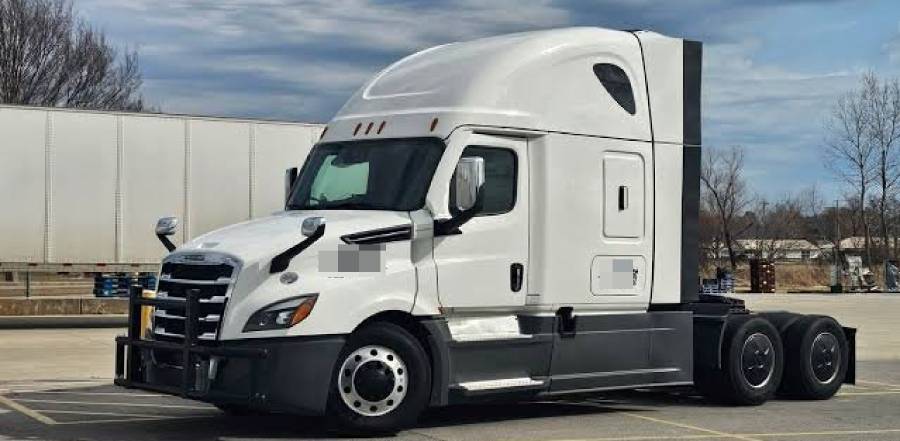
Freightliner Cascadia SPN 521221 FMI 19 indicates a CAN communication fault associated with the Transmission Control Module (TCM). Detroit Diesel identifies this fault as “No CAN Communication,” meaning the transmission control system is experiencing a communication problem that requires electrical and network diagnostics. The fault does not automatically mean the TCM has failed.
The main potential causes of SPN 521221 FMI 19 include insufficient TCM power supply voltage, poor ground connections, damaged Powertrain CAN wiring, loose or corroded connectors, and TCM malfunction. These problems can interrupt communication between electronic control modules and may contribute to transmission warnings, shifting difficulties, or intermittent fault codes. The exact symptoms depend on the vehicle’s transmission configuration and the nature of the communication failure.
Diagnosing this fault requires checking the active diagnostic codes, inspecting the TCM electrical connections, measuring power and ground circuits, and testing Powertrain CAN resistance. Detroit Diesel’s troubleshooting procedure specifies a minimum supply voltage of 11.5 volts, a maximum ground resistance of 3 ohms, and a CAN resistance range of 55–65 ohms under the prescribed test conditions.
This guide explains what SPN 521221 FMI 19 means, its possible causes and symptoms, how to diagnose the fault, and the appropriate repair and verification procedures for affected Freightliner Cascadia trucks.
What Does SPN 521221 FMI 19 Mean on a Freightliner Cascadia?
SPN 521221 FMI 19 indicates a CAN communication fault involving the Transmission Control Module (TCM) on Freightliner Cascadia trucks equipped with the applicable Detroit transmission control system. Detroit Diesel identifies this diagnostic trouble code as “No CAN Communication,” indicating that the expected communication between electronic control modules is not functioning correctly.
The fault code contains two components. SPN 521221 is a manufacturer-specific Suspect Parameter Number that identifies the monitored fault condition, while FMI 19 means “Received Network Data in Error” under the SAE J1939 diagnostic system. Together, these identifiers help technicians locate the affected communication system and select the appropriate troubleshooting procedure.
The TCM manages transmission functions using information exchanged with other electronic control modules through the Powertrain Controller Area Network (CAN). This network carries operating data needed for coordinated engine and transmission control. When communication becomes unavailable or the transmitted information is invalid, the affected control system may record a diagnostic fault.
SPN 521221 FMI 19 does not automatically indicate a defective transmission or TCM. A communication interruption can result from insufficient electrical power, poor grounding, damaged network wiring, or connector problems. The fault identifies a communication problem, but electrical testing is necessary to determine which component or circuit requires repair.
The exact diagnostic procedure depends on the Cascadia model year, transmission configuration, and installed control modules. Technicians should confirm the reporting module and applicable Detroit Diesel service documentation before testing or replacing components.
What Causes SPN 521221 FMI 19 on a Freightliner Cascadia?
The main potential causes of SPN 521221 FMI 19 are TCM power supply problems, poor ground connections, damaged Powertrain CAN wiring, defective electrical connectors, and TCM malfunction. These faults can prevent the transmission controller from communicating correctly with other electronic modules.
The diagnostic process should begin with electrical supply and wiring checks because a communication fault does not establish that the control module itself has failed.
Can a TCM Power or Ground Problem Cause SPN 521221 FMI 19?
Yes. Insufficient TCM supply voltage or excessive resistance in the ground circuit can interfere with module operation and communication. The TCM requires a stable electrical supply and a reliable ground connection to operate its internal electronics and exchange data over the Powertrain CAN network.
Power supply problems can result from damaged wiring, loose terminals, corroded connections, or faults in the electrical distribution circuit. A voltage drop can interrupt normal controller operation, particularly when electrical demand changes. Similarly, excessive ground resistance can create an unstable electrical reference and affect module performance.
Detroit Diesel’s April 2017 troubleshooting procedure for SPN 521221 FMI 19 specifies a minimum supply voltage of 11.5 volts and a maximum ground resistance of 3 ohms under its prescribed test conditions. Readings outside these limits require further investigation of the corresponding electrical circuits.
For example, a corroded TCM ground terminal can increase circuit resistance even when the wiring appears physically intact. Measuring resistance according to the service procedure helps identify an electrical problem that a visual inspection alone may miss.
Can Damaged CAN Wiring Trigger SPN 521221 FMI 19?
Yes. Damaged Powertrain CAN wiring can interrupt communication between the TCM and other electronic control modules, potentially triggering SPN 521221 FMI 19. CAN communication relies on a paired network circuit that carries differential electrical signals between connected controllers.
Broken conductors, short circuits, damaged insulation, corroded terminals, and loose connectors can interfere with signal transmission. Wiring damage may produce a persistent communication failure, while an intermittent connection can cause faults that appear only during vibration or changes in vehicle operating conditions.
The Detroit Diesel troubleshooting procedure includes a Powertrain CAN resistance check with a specified acceptable range of 55–65 ohms under the prescribed test conditions. A reading outside this range indicates that the network circuit requires additional investigation. However, resistance alone cannot identify every communication fault, and an acceptable reading does not rule out intermittent wiring damage.
For example, a partially damaged wire near a harness mounting point may maintain electrical continuity while the truck is stationary but lose contact when the harness moves. Inspecting wiring routing, connector retention, and terminal condition helps locate these intermittent faults.
Can a Faulty TCM Cause SPN 521221 FMI 19?
Yes. A malfunctioning Transmission Control Module can contribute to SPN 521221 FMI 19, but TCM failure should only be considered after the external electrical and communication circuits have been evaluated.
The TCM contains electronic circuitry responsible for processing transmission information and communicating with other controllers. Internal hardware faults can interfere with these functions even when the external power supply, grounding, and network wiring meet the manufacturer’s specifications.
However, a TCM that does not communicate is not necessarily defective. A missing power supply, poor ground connection, or damaged CAN circuit can produce similar diagnostic findings. Replacing the module without checking these conditions may leave the original communication problem unresolved.
For example, a technician may find that the TCM is not responding to a diagnostic scan. Before concluding that the module has failed, the technician should verify the required supply voltage, ground integrity, network resistance, and connector condition using the applicable service procedure.
TCM replacement is justified only when the diagnostic results and manufacturer troubleshooting instructions support module failure. Replacement may also require compatible programming or configuration, depending on the installed transmission system.
What Symptoms Can Occur With SPN 521221 FMI 19?
SPN 521221 FMI 19 can be associated with transmission warning messages, shifting difficulties, intermittent communication failures, and additional diagnostic trouble codes. These symptoms occur when the Transmission Control Module (TCM) cannot reliably exchange information with other electronic control modules. However, the fault code alone does not establish which symptoms will occur on a particular Freightliner Cascadia.
Transmission warnings may appear on the instrument cluster when the vehicle detects a communication problem affecting transmission control. Depending on the transmission configuration and severity of the fault, the driver may experience delayed gear engagement, unavailable gear selection, or abnormal shifting behavior. These symptoms require further diagnosis because mechanical transmission problems and other electronic faults can produce similar results.
Intermittent communication failures can cause warning messages to appear and disappear during vehicle operation. For example, a loose TCM connector or damaged CAN wire may temporarily interrupt communication when the truck encounters road vibration. The fault may subsequently become inactive even though the underlying electrical problem remains.
Additional diagnostic codes can help identify the affected circuit or controller. A technician should examine all related active and inactive faults rather than diagnosing SPN 521221 FMI 19 in isolation. The combination of fault codes, vehicle symptoms, and electrical test results provides a more reliable basis for determining the cause.
How Do You Diagnose SPN 521221 FMI 19 on a Freightliner Cascadia?
Diagnosing SPN 521221 FMI 19 requires confirming the fault, checking TCM power and ground circuits, testing Powertrain CAN communication, and inspecting the associated wiring and connectors. Detroit Diesel’s April 2017 troubleshooting procedure provides electrical specifications for the applicable transmission control system.
Begin by connecting Detroit Diesel DiagnosticLink or a compatible diagnostic tool to the vehicle’s diagnostic interface. Retrieve the stored diagnostic trouble codes, identify the reporting control module, and determine whether SPN 521221 FMI 19 is active or inactive.
Record additional communication and transmission-related faults before clearing any codes. Multiple communication faults may indicate a shared electrical or network problem rather than an isolated TCM failure.
The following specifications apply to the referenced Detroit Diesel troubleshooting procedure. Technicians must confirm that the procedure matches the vehicle’s model year, transmission, and electronic control system before performing electrical measurements.
| Diagnostic Check | OEM Specification |
|---|---|
| TCM power supply voltage | At least 11.5 V |
| TCM ground resistance | 3 Ω or less |
| Powertrain CAN resistance | 55–65 Ω |
| TCM connector | X1, 21-pin |
How Do You Check TCM Power and Ground Circuits?
Check TCM power and ground circuits by measuring the supply voltage and ground resistance at the manufacturer-specified test points. Both circuits must operate correctly because the TCM depends on a stable electrical supply to process transmission information and communicate with other controllers.
Start by locating the TCM and identifying its X1 connector using the applicable Detroit Diesel wiring diagram. The referenced procedure identifies X1 as a 21-pin connector. Confirm the correct connector cavities before attaching test equipment because terminal assignments can differ between vehicle configurations.
For the power supply check, use a digital multimeter to measure voltage at the specified TCM power circuit under the conditions required by the service procedure. The referenced diagnostic specification requires at least 11.5 volts. A reading below this threshold indicates that the supply circuit requires additional investigation.
Inspect the relevant fuses, wiring, terminals, and electrical connections when supply voltage is insufficient. For example, corrosion inside a connector can introduce resistance that produces a voltage drop under electrical load. Battery voltage may appear normal while the voltage reaching the TCM remains below the required level.
Next, test the TCM ground circuit according to the manufacturer’s instructions. Disconnect or isolate the required electrical components and ensure the circuit is de-energized before making resistance measurements. The referenced procedure specifies a maximum ground resistance of 3 ohms.
A resistance reading above the specified limit indicates excessive resistance in the tested ground path. Inspect ground terminals, connector contacts, and wiring for corrosion, loose fasteners, or conductor damage. Repair the confirmed defect and repeat the measurement to verify that the circuit meets the required specification.
Do not replace the TCM solely because a power or ground measurement fails. An out-of-specification reading first requires identifying whether the problem originates in the wiring, connector, electrical supply, or grounding path.
How Do You Test Powertrain CAN Communication?
Test Powertrain CAN communication by checking network resistance, inspecting the wiring harness, and verifying communication with the connected electronic control modules. These checks help identify open circuits, short circuits, termination problems, and damaged electrical connections that interfere with data transmission.
The Powertrain CAN network uses differential signaling between CAN High and CAN Low conductors. Proper wiring continuity and network termination are necessary for reliable communication. A fault in either conductor or an associated connector can prevent the TCM from exchanging information with other controllers.
Before measuring resistance, turn off the ignition and follow the applicable Detroit Diesel procedure for isolating the network and disconnecting components. Never measure resistance on an energized circuit. Use the manufacturer-specified connector terminals and measurement configuration rather than assuming that every diagnostic connector provides the same network access.
The referenced Detroit Diesel procedure specifies a Powertrain CAN resistance range of 55–65 ohms. This range is consistent with the approximate 60-ohm resistance produced by two 120-ohm terminating resistors connected in parallel on a correctly configured CAN network.
A resistance reading substantially above the specified range can indicate an open circuit, disconnected termination, or an incomplete network path. A substantially lower reading can indicate a short circuit or an unintended additional termination. These interpretations guide further testing but do not identify the defective component without additional measurements.
For example, a network reading near 120 ohms may indicate that only one terminating resistor is electrically visible. The technician should inspect the network path and termination arrangement using the vehicle’s wiring diagram rather than immediately replacing a control module.
After resistance testing, inspect the Powertrain CAN wiring harness and TCM X1 connector for damaged insulation, bent terminals, corrosion, loose connections, and improper harness routing. Pay particular attention to locations exposed to vibration, moisture, or repeated movement.
A static resistance test cannot detect every communication problem. Intermittent connections, electrical interference, and signal-quality defects may remain undetected when the truck is stationary. If resistance and wiring checks meet specifications but the fault persists, use DiagnosticLink and the applicable OEM diagnostic procedure to investigate module communication. Advanced signal testing may require an oscilloscope and the appropriate network measurement equipment.
The diagnosis is complete only when the faulty circuit or component has been identified through test results. Normal resistance measurements alone do not prove that the TCM is functioning correctly, just as a communication failure alone does not prove that the TCM needs replacement.
How Do You Fix SPN 521221 FMI 19 on a Freightliner Cascadia?
Fixing SPN 521221 FMI 19 requires repairing the TCM power supply, ground circuit, Powertrain CAN wiring, or control module identified as faulty during diagnosis. The correct repair depends on electrical test results because the code indicates a communication problem rather than a specific failed component.
Start with the TCM power supply when voltage measurements fall below the manufacturer’s specification. Detroit Diesel’s referenced troubleshooting procedure requires at least 11.5 volts at the designated test points. Inspect the associated fuses, electrical terminals, and supply wiring to locate the source of the voltage loss. Replace a blown fuse only after checking for the condition that caused it to fail, and repair damaged conductors or corroded connections using approved electrical repair methods.
A faulty ground circuit requires restoring a reliable electrical connection between the TCM and the designated grounding point. Clean corroded terminals, secure loose connections, and repair damaged ground wiring when testing confirms excessive resistance. The referenced Detroit Diesel procedure specifies a maximum resistance of 3 ohms under its prescribed test conditions. Repeat the ground circuit test after completing repairs to confirm that resistance meets the applicable specification.
Repair Powertrain CAN wiring when testing identifies an open circuit, short circuit, damaged conductor, or defective connector. Inspect the affected harness section and restore the circuit using manufacturer-approved wiring repair procedures. Preserve the original twisted-pair configuration, conductor specifications, and harness routing because improper repairs can introduce signal interference or additional communication problems.
For example, a damaged CAN wire near a harness mounting bracket may require replacement of the affected wiring section and correction of the mounting condition that caused the damage. Simply reconnecting the conductor without addressing abrasion or excessive movement can allow the fault to return.
Damaged connector terminals also require attention. Bent pins, corrosion, weak terminal contact, and broken connector locks can interrupt communication even when the wiring harness passes a continuity test. Repair or replace affected terminals and connector components according to the applicable service instructions. Avoid applying excessive force to connector pins or using unapproved repair materials.
Replace the Transmission Control Module only when the manufacturer’s diagnostic procedure confirms that replacement is necessary. A TCM that fails to communicate may still be functioning correctly if its power supply, ground circuit, or CAN connection is defective. Confirm these external circuits before condemning the module.
When TCM replacement is required, use a compatible replacement unit and follow the applicable Detroit Diesel installation, programming, and configuration procedures. Depending on the transmission system, the replacement module may require software configuration or calibration before normal operation can be restored.
After completing the identified repair, reconnect all electrical components, secure the wiring harness, and restore the vehicle to its specified operating configuration. Perform the required diagnostic checks before returning the truck to service.
How Do You Verify That SPN 521221 FMI 19 Has Been Fixed?
Verify the repair by confirming that SPN 521221 FMI 19 is no longer active, TCM communication has been restored, and the transmission operates correctly under the applicable test conditions. Clearing the diagnostic code without correcting its underlying cause does not establish that the fault has been repaired.
Connect DiagnosticLink or a compatible diagnostic tool and retrieve the current fault information. Confirm that the affected control modules communicate correctly and check for additional active communication or transmission-related codes. If the original fault remains active, continue diagnosis rather than repeatedly clearing the code.
When the repair involves power, ground, or CAN wiring, repeat the electrical measurements that originally failed. For example, a repaired CAN circuit should meet the resistance specification under the prescribed test conditions. Compare the new readings with the original measurements to confirm that the identified electrical defect has been corrected.
After electrical verification, perform the transmission functional checks required by the applicable service procedure. Confirm normal gear selection and monitor for warning messages or recurring communication faults. Conduct a road test only when the vehicle is safe to operate and the manufacturer’s procedure permits it.
The repair is successful when the original fault condition no longer occurs and the affected system passes the required diagnostic and functional checks. If SPN 521221 FMI 19 returns, investigate intermittent wiring faults, connector problems, or other unresolved communication issues before replacing additional components.
What Does FMI 19 Mean in the SAE J1939 Fault Code System?
FMI 19 means “Received Network Data in Error” in the SAE J1939 diagnostic system. It identifies a fault condition in which an electronic control module receives network information that is considered invalid or incorrect. On an applicable Freightliner Cascadia transmission control system, SPN 521221 FMI 19 is identified by Detroit Diesel as “No CAN Communication.”
SAE J1939 diagnostic trouble codes combine a Suspect Parameter Number (SPN) with a Failure Mode Identifier (FMI). The SPN identifies the affected parameter or manufacturer-defined fault condition, while the FMI describes the type of failure detected. SPN 521221 is manufacturer-specific, so its exact interpretation requires the appropriate Detroit Diesel diagnostic documentation.
FMI 19 does not identify a defective sensor, wiring harness, or control module by itself. For example, incorrect network data can result from a communication problem involving another controller, while a complete communication interruption may be associated with damaged wiring or an unavailable module. The reporting controller and manufacturer-specific fault definition determine which diagnostic procedure applies.
Technicians should therefore interpret FMI 19 together with SPN 521221, the reporting module, and any additional diagnostic codes rather than treating it as a standalone diagnosis.
Read more: Freightliner Cascadia Fuel Pressure Problems & Fixes
What Is the Difference Between Active and Inactive SPN 521221 FMI 19 Faults?
An active SPN 521221 FMI 19 fault indicates that the reporting control module currently detects the communication problem, while an inactive fault indicates that the condition was previously recorded but is not currently detected. This distinction helps technicians determine whether the problem is continuous or intermittent.
An active fault generally requires immediate investigation of the affected communication system. For example, if the TCM cannot communicate because its power supply is interrupted, the fault may remain active until the electrical problem is corrected. The diagnostic tool can help identify the reporting module and any related active codes.
An inactive fault can result from a temporary communication interruption. Loose connector terminals, damaged wiring, and unstable electrical connections may produce faults that disappear when normal contact is restored. Road vibration or temperature changes can cause an intermittent connection to fail again during operation.
For example, SPN 521221 FMI 19 may become inactive after a damaged connector temporarily regains electrical contact. Although the warning may disappear, the underlying defect can remain.
An inactive fault does not prove that the problem has been permanently repaired. Review the stored fault history, occurrence information when available, and related diagnostic codes. Preserve this information before clearing faults, then verify the affected circuits and monitor for recurrence under appropriate operating conditions.
Can You Drive a Freightliner Cascadia With SPN 521221 FMI 19?
Driving with SPN 521221 FMI 19 depends on the vehicle’s transmission operation, active warning messages, and the severity of the communication failure. The fault code alone cannot establish whether a Freightliner Cascadia is safe to operate.
A communication fault involving the TCM can interfere with the information required for normal transmission control. Depending on the installed transmission system and the nature of the failure, the truck may experience shifting difficulties, unavailable gear selection, or other transmission-related warnings. These conditions can affect vehicle control and require prompt evaluation.
Stop in a safe location if the transmission fails to engage the selected gear, unexpectedly changes operating behavior, or displays a warning requiring the driver to stop. Do not continue driving when the truck cannot maintain predictable transmission operation. Follow the vehicle’s operator manual and obtain qualified roadside assistance or towing when necessary.
If the fault is inactive and the transmission appears to operate normally, the vehicle still requires diagnostic inspection. An intermittent CAN communication problem can return without warning, particularly when damaged wiring or loose electrical connections are involved. Normal operation at one moment does not establish that the fault has been resolved.
For example, a truck with an intermittent TCM connector problem may shift normally while stationary but experience communication interruptions during road vibration. Inspecting the connector and confirming stable communication provides a more reliable assessment than relying only on the absence of a dashboard warning.
The safest approach is to diagnose SPN 521221 FMI 19 before returning the truck to normal service. Confirm the communication fault has been corrected and the transmission passes the required functional checks. A qualified diesel technician should determine whether the vehicle can be operated safely when the fault remains unresolved.