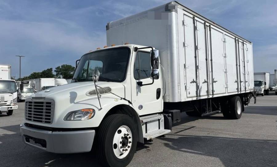
Freightliner M2 electrical problems include intermittent power loss, starting failures, flickering dashboard lights, malfunctioning accessories, and electronic control module faults. These issues can result from weak batteries, faulty alternators, corroded ground connections, damaged wiring, defective relays, or power distribution failures. The exact cause depends on the affected electrical circuits, vehicle configuration, and operating conditions.
The Freightliner Business Class M2 uses interconnected electrical and electronic systems to control engine starting, lighting, instrument displays, and vehicle functions. A loose battery connection can interrupt power to multiple components, while a damaged wiring harness may cause intermittent failures that appear only during vibration or wet conditions. Problems involving the Bulkhead Module (BHM) or J1939 communication network can also disrupt electrical functions, although these symptoms do not automatically indicate a defective control module.
Diagnosing Freightliner M2 electrical problems requires a systematic inspection of battery voltage, charging performance, fuses, relays, wiring connections, and diagnostic trouble codes. Testing the power supply and ground circuits before replacing electronic modules helps identify the underlying fault and avoid unnecessary repair expenses. This guide explains common electrical symptoms, their causes, practical diagnostic procedures, repair solutions, estimated costs, and preventive maintenance methods.
What Are the Most Common Freightliner M2 Electrical Problems?
The most common Freightliner M2 electrical problems involve intermittent power loss, starting failures, flickering dashboard lights, malfunctioning headlights, and electrical accessory failures. These symptoms are associated with faults in the battery, alternator, wiring harness, ground connections, power distribution circuits, and electronic control systems. Identifying which components stop working helps narrow down the affected circuit before electrical testing begins.
Intermittent electrical power loss occurs when the vehicle’s electrical supply is interrupted by loose battery terminals, corroded cables, damaged wiring, or high-resistance ground connections. A poor connection can cause dashboard displays, lights, or other electrical equipment to shut off unexpectedly. Vibrations from driving may temporarily restore or interrupt the connection, making the problem difficult to reproduce while the truck is stationary.
Starting failures include situations where the Freightliner M2 does not crank, cranks slowly, or cranks without starting. Weak batteries, defective starter relays, damaged starter cables, and faulty ignition circuits can prevent the starter motor from operating correctly. A crank-no-start condition requires a different diagnostic approach because the starter is already turning the engine, and the fault may involve engine management, fuel delivery, or electronic communication.
Flickering dashboard lights and instrument cluster malfunctions can result from unstable charging voltage, loose ground connections, damaged connectors, or interrupted communication between electronic modules. Drivers may notice gauges resetting, warning indicators appearing unexpectedly, or the instrument display shutting down. These symptoms require testing the instrument cluster’s power and ground circuits before concluding that the cluster or a control module has failed.
Headlight, turn signal, and electrical accessory failures can originate from blown fuses, defective relays, damaged wiring, or control circuit faults. A single inoperative headlight generally directs troubleshooting toward its individual circuit, while several unrelated accessories failing simultaneously may indicate a shared power supply, ground, or control problem. Freightliner M2 configurations differ by model year and installed equipment, so circuit identification should follow the appropriate vehicle wiring diagram.
Electronic control and communication faults can affect multiple vehicle functions when modules lose electrical power, ground continuity, or network communication. The Bulkhead Module (BHM), Chassis Module, and J1939 communication network are relevant diagnostic areas on applicable Freightliner M2 configurations. However, communication-related fault codes do not independently confirm module failure because low voltage, damaged connectors, and network wiring faults can produce similar symptoms.
The affected components, timing of the failure, and diagnostic trouble codes provide the initial evidence needed to distinguish a localized circuit problem from a vehicle-wide electrical fault.
What Causes Freightliner M2 Electrical Problems?
Freightliner M2 electrical problems result from five main fault categories: battery deterioration, charging system failures, damaged wiring, poor ground connections, and power distribution or electronic control faults. These failures disrupt the voltage supply, current flow, or communication signals required for vehicle operation. Environmental exposure, engine vibration, connector corrosion, and component aging contribute to electrical deterioration, particularly in trucks operating under demanding commercial conditions.
How Do Battery and Alternator Problems Cause Electrical Failures?
Battery and alternator problems cause Freightliner M2 electrical failures by reducing or destabilizing the voltage supplied to the vehicle’s electrical circuits. The batteries provide power for engine starting and support electrical loads, while the alternator supplies electrical energy and recharges the batteries when the engine operates. A failure in either component can affect starting performance, electronic controls, lighting, and other electrical equipment.
A deteriorated battery develops reduced capacity or increased internal resistance, limiting its ability to deliver the high current required by the starter motor. Corroded battery terminals and damaged cables create additional resistance, producing voltage drops under load. A battery may display an acceptable voltage without a load but fail to maintain sufficient voltage during cranking. For example, a Freightliner M2 equipped with a nominal 12-volt electrical system may crank slowly despite showing approximately 12.6 volts at rest because the battery voltage drops excessively when the starter engages.
Alternator failures affect electrical performance after the engine starts. Worn internal components, faulty voltage regulation, damaged charging cables, or drive belt problems can prevent the alternator from maintaining the required system voltage. Undercharging gradually depletes battery reserves, while excessive charging voltage can damage batteries and sensitive electronics. Charging voltage must be evaluated against the specifications for the installed alternator and vehicle configuration rather than relying on a single universal value.
How Do Wiring and Ground Connection Problems Affect the Electrical System?
Damaged wiring and poor ground connections cause Freightliner M2 electrical problems by interrupting current flow, increasing circuit resistance, or creating unintended electrical paths. Commercial trucks experience repeated vibration, temperature changes, moisture exposure, and mechanical movement that can deteriorate wiring insulation, connectors, and grounding points over time.
Wiring harness damage occurs when electrical cables rub against metal brackets, chassis components, or other surfaces. Continuous friction can remove insulation and expose conductors, creating short circuits or open circuits. Moisture entering damaged connectors promotes corrosion, which increases electrical resistance and restricts current flow. For example, a corroded connector supplying a lighting circuit may allow the lamps to operate normally at first but cause intermittent failures as resistance increases or vibration changes the contact between terminals.
Ground connection failures produce similar symptoms because electrical circuits require a reliable return path to the battery. Loose ground straps, corroded chassis attachment points, and damaged ground cables can create excessive voltage drops when electrical loads operate. Shared ground faults may affect several components simultaneously, including dashboard instruments, lighting circuits, and electronic modules.
A voltage drop test performed while the affected circuit is operating helps identify excessive resistance in wiring and ground connections. This method is particularly useful for locating faults that remain undetected during basic continuity testing.
How Can Faulty Control Modules Cause Electrical Problems?
Faulty electronic control modules can cause Freightliner M2 electrical problems by interrupting the operation of systems that depend on electronic switching, monitoring, and communication. Depending on the model year and vehicle configuration, the Bulkhead Module (BHM), Chassis Module, Engine Control Module (ECM), and other controllers manage or exchange information related to vehicle electrical functions.
The Bulkhead Module processes electrical inputs and controls designated vehicle functions according to its configuration. The Chassis Module manages applicable chassis-related electrical outputs, while the ECM controls engine-related operations. These controllers depend on stable battery voltage, reliable ground connections, functional wiring, and communication networks to operate correctly. A disruption in any of these supporting circuits can produce symptoms resembling internal module failure.
Freightliner M2 electronic controllers communicate through vehicle data networks, including J1939 on applicable systems. Damaged communication wiring, corroded connectors, incorrect network resistance, or loss of module power can interrupt message transmission. For example, a module that loses its power supply may stop communicating with other controllers, causing multiple communication-related diagnostic trouble codes even though the module itself remains functional.
Internal control module failures can also occur because of electronic component deterioration, moisture intrusion, or electrical damage. However, module replacement should follow verification of power supply, ground integrity, network communication, and associated wiring. Replacing a controller without identifying the actual fault can leave the original electrical problem unresolved and introduce additional programming or configuration requirements.
How Do You Diagnose Freightliner M2 Electrical Problems?
Diagnosing Freightliner M2 electrical problems requires checking the battery and charging system, testing fuses and wiring circuits, and examining electronic control module communication. A digital multimeter, battery load tester, vehicle-specific wiring diagram, and compatible heavy-duty diagnostic scanner help identify electrical faults. The diagnostic sequence should begin with the affected circuit’s power supply and ground connections before progressing to control modules or network components.
How Do You Test the Battery and Charging System?
To test the Freightliner M2 battery and charging system, measure battery voltage with the engine off, observe voltage during cranking, and check alternator output while the engine runs. These measurements help distinguish battery deterioration, excessive circuit resistance, and charging system failures.
Begin by inspecting the battery terminals, cable connections, and battery case for corrosion, physical damage, or loose connections. On a nominal 12-volt system, a fully charged lead-acid battery typically measures approximately 12.6–12.8 volts after resting without charging or significant electrical loads. A reading near 12.2 volts indicates a substantially reduced state of charge, although voltage interpretation depends on battery chemistry, temperature, and resting conditions. Trucks equipped with multiple batteries require inspection of individual battery condition and interconnecting cables.
Next, perform a battery load or conductance test using equipment appropriate for the installed batteries. Monitor voltage during engine cranking to identify excessive voltage drops. A conventional 12-volt lead-acid battery may use approximately 9.6 volts at 70°F (21°C) as a reference during a specified load test, but this is not a universal cranking-voltage limit. Battery manufacturer specifications and temperature corrections determine the applicable acceptance criteria.
Start the engine and measure charging voltage at the battery terminals. Many conventional 12-volt charging systems operate around 13.5–14.8 volts under suitable conditions, although the correct range depends on alternator regulation, temperature, electrical demand, and vehicle specifications. Repeat the measurement with headlights, HVAC blower, and other electrical loads operating. If charging voltage remains below specification, inspect the alternator drive belt, charging cables, ground connections, and alternator output before replacing components.
How Do You Check Fuses, Relays, and Wiring?
To check Freightliner M2 fuses, relays, and wiring, identify the affected electrical circuit using the correct vehicle wiring diagram, verify its power supply, and test for excessive resistance or interrupted connections. Fuse panel locations, relay assignments, and power distribution arrangements vary by model year and vehicle configuration, making VIN-specific service information essential.
Start by identifying the fuse protecting the malfunctioning component. With the circuit energized under the appropriate operating conditions, use a multimeter or suitable test light to check voltage at both fuse test points. Voltage on the supply side but not the load side indicates an open fuse, provided the circuit is correctly powered. A blown fuse must be replaced with the specified amperage rating only after investigating possible short circuits or overloaded components.
Relay testing requires checking the control circuit and the switched power circuit separately. Confirm that the relay receives the required control signal and that its contacts deliver power to the connected load. A relay that clicks does not necessarily have functional contacts, because internal resistance or contact damage can prevent sufficient current from reaching the component. Relay substitution is appropriate only when the replacement has matching electrical specifications and terminal functions.
Inspect wiring harnesses for damaged insulation, loose connectors, corrosion, and contact with sharp metal surfaces. Pay particular attention to wiring near battery compartments, chassis attachment points, and areas exposed to road spray or engine vibration. A voltage drop test performed under electrical load can reveal high-resistance connections that appear normal during visual inspection.
For example, measuring voltage between the battery negative terminal and a component’s ground terminal while that component operates can reveal excessive resistance in the ground return path. Compare the result with the circuit’s service specifications. Perform continuity and resistance measurements only after isolating the circuit and disconnecting power as required by the manufacturer’s procedures.
How Do You Diagnose Control Module and Communication Faults?
To diagnose Freightliner M2 control module and communication faults, retrieve diagnostic trouble codes, verify module power and ground circuits, and inspect the vehicle communication network. These steps distinguish internal controller failures from wiring faults, unstable voltage supplies, and interrupted data communication.
Connect a compatible heavy-duty diagnostic scanner to the vehicle’s diagnostic connector and identify the electronic controllers that respond. Read active and stored diagnostic trouble codes, recording the reporting module, fault status, and operating conditions when available. Freightliner M2 configurations using SAE J1939 communication may report faults through Suspect Parameter Numbers (SPNs) and Failure Mode Identifiers (FMIs). An SPN identifies the affected parameter or system, while the FMI describes the reported failure condition.
When a controller does not communicate, inspect its battery supply, ignition-controlled power, ground connections, and relevant fuses before considering replacement. A missing communication response does not establish that the controller is defective. For example, an interrupted power feed to the Bulkhead Module can prevent communication even when its internal electronics remain operational.
J1939 network testing may include checking wiring continuity, connector condition, and network termination. A correctly configured high-speed J1939 CAN segment with two 120-ohm terminating resistors typically measures approximately 60 ohms between CAN High and CAN Low when the network is de-energized and isolated under the appropriate test conditions. Different network architectures, additional circuits, and connected components can affect the measurement, so the applicable Freightliner service procedure must determine the correct testing method.
Inspect communication wiring for open circuits, short circuits, damaged insulation, and moisture-contaminated connectors. Use an oscilloscope when necessary to examine CAN signal behavior and identify communication disturbances that resistance measurements cannot reveal. Avoid probing or disconnecting electronic modules while circuits are energized unless the manufacturer explicitly specifies the procedure.
After identifying and repairing the electrical fault, clear diagnostic codes according to the service procedure, operate the affected systems, and scan the vehicle again. Confirming normal voltage, circuit operation, and module communication establishes whether the repair resolved the original problem.
How Do You Fix Freightliner M2 Electrical Problems?
Fixing Freightliner M2 electrical problems involves repairing damaged connections, replacing defective electrical components, restoring wiring integrity, and correcting electronic control faults. The appropriate repair depends on diagnostic results because similar symptoms can originate from different circuits. Confirming the underlying cause before replacing components prevents unnecessary expenses and recurring electrical failures.
Repairing corroded battery terminals and ground connections restores reliable current flow between the batteries, starter, chassis, and electrical components. Disconnect the batteries according to the manufacturer’s service procedure, normally removing the negative connection first where applicable. Inspect terminals, cable ends, and ground attachment points for corrosion, loose fasteners, and damaged conductors. Clean serviceable connections with appropriate electrical cleaning materials and replace cables showing broken strands, severe corrosion, or deteriorated insulation. Reconnect and tighten terminals to the specified torque, then perform a voltage drop test under load to confirm the repair.
Replacing a defective battery or alternator corrects electrical failures caused by inadequate power storage or charging output. Replace batteries that fail the specified load or conductance tests after verifying their state of charge and connection condition. In multi-battery configurations, test each battery individually and follow the manufacturer’s requirements for matching battery capacity, type, and condition. Alternator replacement is appropriate when testing confirms insufficient output or faulty regulation after excluding drive belt, cable, and ground problems. Following installation, measure charging voltage under different electrical loads to verify proper operation.
Repairing damaged wiring harnesses eliminates open circuits, short circuits, and high-resistance connections. Locate the damaged section using the vehicle wiring diagram and electrical measurements before disconnecting the circuit. Replace damaged conductors with wiring that meets the original circuit’s gauge, insulation, temperature, and current requirements. Use approved automotive terminals, connectors, and sealed splices suitable for the installation environment. Route repaired wiring away from sharp edges, excessive heat, and moving components, and secure the harness to prevent vibration damage. Safety-critical circuits and communication wiring may require manufacturer-approved repair procedures or harness replacement rather than generic splicing.
Replacing faulty fuses and relays restores power to electrical circuits when testing confirms a failed protective or switching component. Install replacement fuses with the specified amperage rating and compatible relays with the correct terminal arrangement and electrical characteristics. A fuse that blows repeatedly indicates an unresolved circuit fault, such as damaged insulation, a shorted component, or excessive current draw. Never install a higher-rated fuse or bypass circuit protection to keep an electrical component operating.
Repairing power distribution and electronic control faults requires verifying the affected module’s power supply, ground connections, output circuits, and communication network. Replace a Power Distribution Module, Bulkhead Module, or Chassis Module only when diagnostic testing confirms an internal failure. A replacement controller may require configuration, programming, or parameter synchronization using compatible diagnostic equipment. Installing a module without completing these procedures can leave vehicle functions inoperative or create additional diagnostic faults.
Verifying electrical repairs is necessary to confirm that the original problem has been eliminated. Recheck battery and charging voltage, measure circuit voltage drops, operate the affected components, and inspect repaired connections under normal electrical loads. When electronic controllers are involved, clear relevant diagnostic trouble codes using the approved procedure and perform another system scan. For intermittent failures, repeat testing under the operating conditions that originally triggered the problem, such as engine vibration or accessory operation. A successful repair restores normal electrical function without recurring symptoms or related active fault codes.
How Much Does It Cost to Fix Freightliner M2 Electrical Problems?
Freightliner M2 electrical repair costs depend on the failed component, diagnostic labor, replacement parts, and the complexity of the electrical system. Basic repairs involving battery terminals, fuses, or relays generally cost less than extensive wiring harness repairs or electronic control module replacement. Commercial truck repair shops also charge different labor rates based on location, technician expertise, and diagnostic equipment requirements.
The following table provides illustrative repair cost ranges for Freightliner M2 electrical problems in the United States. These are preliminary budgeting estimates, not verified current shop quotes or model-specific prices.
| Electrical Repair | Estimated Cost (USD) |
|---|---|
| Electrical system diagnosis | $100–$250 |
| Battery replacement | $150–$400 per battery |
| Alternator replacement | $400–$1,200 |
| Battery cable or ground repair | $100–$350 |
| Fuse or relay replacement | $50–$200 |
| Wiring harness repair | $150–$800+ |
| Electronic control module replacement | $500–$2,000+ |
Battery and charging system repairs vary according to battery capacity, alternator specifications, and installation labor. Freightliner M2 trucks equipped with multiple batteries may require additional testing and replacement expenses. High-output alternators and specialized commercial truck components can also increase repair costs compared with standard automotive electrical parts.
Wiring and control module repairs can become more expensive because locating an intermittent fault requires additional diagnostic time. A technician may need to inspect multiple connectors, trace circuits through wiring diagrams, and perform voltage drop or communication network tests. Electronic module replacement can add programming and configuration charges, particularly when the replacement controller must be matched to the vehicle’s electrical configuration.
The most reliable way to control repair expenses is to confirm the failed circuit before authorizing component replacement. A written estimate should separate diagnostic labor, replacement parts, programming, and final system testing. This helps distinguish the cost of identifying the electrical problem from the cost of correcting it.
Do Freightliner M2 Electrical Problems Vary by Model Year?
Freightliner M2 electrical problems vary by model year because electrical architecture, power distribution arrangements, electronic control modules, and wiring configurations have changed across different vehicle generations. The Freightliner Business Class M2 family includes multiple models and equipment configurations, so trucks with similar exterior designs do not necessarily use identical electrical systems.
Older Freightliner M2 configurations may use different control module arrangements, fuse assignments, and wiring connections from later vehicles. Electrical troubleshooting on these trucks requires identifying the installed components rather than assuming that every M2 uses the same Bulkhead Module, Chassis Module, or power distribution layout. Battery and ground faults remain relevant across model years, but circuit locations and diagnostic procedures can differ.
Newer Freightliner M2 configurations, including vehicles from the M2 Plus generation introduced for the 2023 model year, incorporate updated electronic systems and vehicle features. Changes in control architecture, instrumentation, and electrical equipment can affect diagnostic access and repair procedures. A wiring diagram or module replacement procedure intended for an earlier Freightliner M2 should not be applied to a newer configuration without confirming compatibility.
Differences between the Freightliner M2 106 and M2 112 also require attention. These models can have different engine options, electrical loads, chassis equipment, and body configurations. Additional equipment such as liftgates, refrigeration units, auxiliary lighting, or vocational body controls introduces electrical circuits that may not appear in a standard chassis diagram. Faults in aftermarket or body-builder wiring can also affect the vehicle’s electrical supply.
Accurate diagnosis requires identifying the vehicle identification number (VIN), model year, engine configuration, and installed electrical equipment. Technicians should use the corresponding Freightliner service documentation, wiring diagrams, and diagnostic procedures to locate the correct circuits and determine component specifications. This prevents incorrect fuse identification, unnecessary module replacement, and repairs based on incompatible electrical configurations.
Read more: Freightliner M2 Overheating: Causes & Fixes
How Can You Prevent Freightliner M2 Electrical Problems?
Preventing Freightliner M2 electrical problems requires regular battery inspections, charging system testing, wiring harness maintenance, and protection against moisture and corrosion. Preventive maintenance reduces the risk of unexpected electrical failures by identifying deteriorating components before they interrupt starting, lighting, or electronic control functions. Inspection frequency should follow Freightliner maintenance requirements and account for vehicle mileage, operating conditions, and electrical equipment usage.
Inspecting batteries and electrical connections helps prevent voltage drops and intermittent power loss. Check battery terminals for corrosion, loose connections, and damaged cables during scheduled maintenance. Inspect chassis and engine ground straps for deterioration, particularly where connections are exposed to road salt, moisture, and vibration. Corroded terminals should be cleaned or replaced according to their condition, while loose connections must be tightened to the manufacturer’s specifications. Battery condition testing also helps identify reduced capacity before starting failures occur.
Maintaining the charging system prevents battery depletion and unstable electrical voltage. Check alternator output, drive belt condition, and charging cable connections during routine service. A deteriorated belt can reduce alternator performance, while excessive resistance in charging cables can prevent batteries from receiving adequate charging voltage. Trucks operating with additional electrical loads, such as auxiliary lighting or refrigeration equipment, require particular attention to charging capacity and battery condition.
Protecting wiring harnesses and electrical connectors reduces failures caused by vibration, abrasion, and moisture intrusion. Inspect wiring near chassis rails, engine compartments, battery boxes, and body-mounted equipment for damaged insulation or unsecured cables. Replace broken retaining clips, restore protective conduit, and secure loose harness sections using approved mounting methods. Electrical connectors should remain properly sealed, especially in areas exposed to road spray. Damaged seals and corroded terminals require appropriate repair rather than temporary external coverings.
Monitoring electrical warning signs helps identify developing faults before they affect vehicle operation. Slow engine cranking, intermittent dashboard resets, dimming lights, and recurring diagnostic trouble codes indicate conditions that warrant inspection. Record when symptoms occur, including engine temperature, weather conditions, and electrical loads in use. These observations help technicians reproduce intermittent failures and locate the affected circuits.
Preventive maintenance should also include checking electrical modifications installed by body builders or previous owners. Improperly connected accessories, overloaded circuits, and unprotected wiring can introduce faults into the original electrical system. Any additional equipment should use correctly rated wiring, circuit protection, and connection points approved for the vehicle configuration.
When Should You Take a Freightliner M2 to a Professional Technician?
A Freightliner M2 should be inspected by a qualified commercial truck technician when electrical problems involve repeated power loss, recurring fuse failures, control module communication faults, or safety-critical vehicle systems. These conditions require specialized diagnostic equipment and electrical testing procedures that extend beyond basic battery and fuse inspections.
Repeated electrical power loss requires professional diagnosis when the engine, dashboard, or multiple electrical components shut down unexpectedly. A technician can perform loaded circuit testing, inspect shared power and ground connections, and identify intermittent faults that are difficult to reproduce. The truck should not remain in service when electrical interruptions affect engine operation, exterior lighting, or other safety-related functions.
Recurring fuse failures or electrical overheating indicate potentially hazardous circuit conditions. Repeatedly blown fuses can result from short circuits, damaged wiring insulation, or excessive current draw. Burning smells, melted connectors, smoke, or unusually hot electrical components require immediate attention. Stop operating the vehicle safely and arrange professional inspection rather than replacing fuses repeatedly or bypassing circuit protection.
Electronic control module and J1939 communication problems also warrant professional diagnosis when basic power supply checks do not identify the fault. Qualified technicians can use compatible diagnostic software, vehicle wiring diagrams, and network testing equipment to evaluate controller communication and electrical integrity. Module replacement or programming should follow confirmed diagnostic findings and the applicable Freightliner service procedures.
Professional electrical repair is especially important when faults affect starting reliability, braking-related electronics, engine operation, or required lighting. Resolving these problems before returning the truck to service helps prevent additional component damage, unexpected downtime, and unsafe operating conditions.