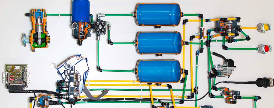
A Freightliner air suspension system diagram shows how air springs, height control valves, air reservoirs, and pneumatic lines connect to support the truck’s weight and maintain proper ride height. The diagram identifies the main suspension components, their locations, and the airflow paths that regulate air pressure as vehicle loads change.
Freightliner trucks use different air suspension configurations depending on the model, axle arrangement, and suspension design. Systems such as Freightliner AirLiner rely on compressed air to support the chassis, while height control valves regulate airflow into and out of the air springs. Shock absorbers control suspension movement, and mechanical components such as torque rods help maintain axle alignment. Understanding these connections makes it easier to identify suspension components and trace potential faults.
This guide explains the Freightliner air suspension system diagram, including component functions, air line routing, and the operating principles behind automatic ride height adjustment. It also covers differences between Freightliner Cascadia, Columbia, and M2 suspension configurations, common problems such as air leaks and uneven ride height, and how to locate the correct diagram for a specific truck. Because suspension layouts vary, model-specific service documentation is essential for accurate diagnosis and repair.
What Does a Freightliner Air Suspension System Diagram Show?
A Freightliner air suspension system diagram shows the arrangement of air springs, height control valves, air reservoirs, pneumatic lines, and suspension hardware that support the truck’s chassis and regulate ride height. The diagram illustrates how compressed air moves through the suspension circuit and how individual components interact when the vehicle’s load changes.
Freightliner suspension diagrams generally fall into two categories: component layout diagrams and pneumatic schematics. A component layout diagram identifies the physical positions of air springs, shock absorbers, suspension brackets, torque rods, and control valves relative to the frame and axles. A pneumatic schematic illustrates the connections between the compressed air supply, control valves, air lines, and air springs. Both diagram types serve different purposes: layout diagrams help locate components, while pneumatic schematics help trace airflow and identify potential pressure losses.
In a typical mechanically controlled rear air suspension system, compressed air travels from the vehicle’s air supply through a height control valve before reaching the air springs. The valve responds to changes in the distance between the chassis and axle, allowing air to enter or leave the springs to restore the specified ride height. Some configurations include additional valves, separate air circuits, or electronic suspension controls that change the routing shown in the diagram.
The correct Freightliner suspension diagram depends on the truck’s model, production year, axle configuration, and installed suspension system. A general schematic explains operating principles, but it does not establish the exact hose routing, valve port assignments, or component locations for every Freightliner truck. Technicians should verify these details against the vehicle-specific service documentation before performing repairs.
What Are the Main Components of a Freightliner Air Suspension System?
The main components of a Freightliner air suspension system include air springs, height control valves, air reservoirs, pneumatic lines, shock absorbers, and mechanical suspension linkages. Each component performs a specific function in supporting vehicle loads, maintaining ride height, controlling axle movement, or distributing compressed air.
The following table identifies the principal components and their functions in a typical Freightliner rear air suspension configuration.
| Component | Primary Function |
|---|---|
| Air springs (air bags) | Support vehicle weight using compressed air |
| Height control valve | Regulates air supply and exhaust to maintain ride height |
| Air reservoir | Stores compressed air for pneumatic systems |
| Air lines and fittings | Transfer compressed air between connected components |
| Shock absorbers | Dampen suspension oscillations |
| Torque rods | Control axle movement and maintain axle positioning |
| Suspension brackets | Connect suspension components to the chassis and axle |
| Valve linkage | Transfers suspension height changes to the height control valve |
The exact number and arrangement of these components depend on the suspension configuration. For example, tandem-drive-axle systems use suspension assemblies designed to support and control two rear drive axles, while single-rear-axle configurations have different mechanical layouts.
What Do Air Springs Do in a Freightliner Suspension System?
Air springs support the truck’s chassis using pressurized air and allow the suspension to accommodate changes in vehicle load. They replace or supplement conventional mechanical spring arrangements, depending on the suspension design. A typical rolling-lobe air spring consists of a reinforced rubber bellows, mounting components, and a piston that guides the bellows during suspension movement.
Air spring load capacity depends on internal air pressure and the effective area of the spring. As cargo weight increases, the chassis moves closer to the axle, causing the height control system to admit additional compressed air. Increasing air pressure raises the supporting force until the suspension returns to its specified ride height. When the load decreases, the control system releases excess air to restore the same height.
Air springs also isolate the chassis from road-induced vibrations. The compressed air inside each spring changes volume as the suspension moves, providing a compliant connection between the axle and frame. Shock absorbers work alongside the air springs to control repeated compression and rebound. Without effective damping, the chassis can continue oscillating after crossing bumps or uneven pavement.
A damaged air spring can cause reduced ride height, visible chassis leaning, or repeated air compressor operation. Cracks in the rubber bellows, leaks around mounting connections, and deterioration near the rolling surface are potential failure points. The suspension diagram helps identify the affected spring and its associated air supply connection, although physical inspection is necessary to confirm the source of a leak.
How Does the Height Control Valve Regulate Ride Height?
The height control valve maintains the specified distance between the Freightliner chassis and axle by adding or exhausting compressed air from the air springs. In a mechanically controlled suspension, the valve is typically attached to the frame and connected to the axle or suspension assembly through an operating linkage.
A conventional mechanical height control valve has three operating states:
- Fill: When the chassis drops below the specified ride height, the linkage moves the valve toward its supply position, allowing compressed air to enter the air springs.
- Neutral: When the suspension reaches its specified height, the valve closes its supply and exhaust passages, maintaining the air volume needed to support the load.
- Exhaust: When the chassis rises above the specified ride height, the valve releases air from the springs until the suspension returns to its normal position.
For example, loading additional cargo onto a Freightliner truck compresses the rear suspension and reduces the distance between the frame and axle. The resulting linkage movement activates the height control valve, which admits compressed air into the rear air springs. As the chassis rises to the specified position, the valve returns to neutral and stops additional airflow.
Height control valves may incorporate a response delay to prevent unnecessary inflation and deflation during brief suspension movements. The actual valve arrangement, linkage geometry, and adjustment procedure vary by suspension design. Incorrect linkage adjustment can produce excessive or insufficient ride height, affecting suspension travel, driveline geometry, and component wear.
Air reservoirs and pneumatic lines supply the compressed air required for this process. The reservoir stores air generated by the vehicle’s compressed-air system, while pneumatic lines and fittings connect the supply circuit to the height control valve and air springs. Shock absorbers and torque rods provide mechanical control of suspension movement but do not regulate pneumatic pressure.
Together, these components form a suspension system that supports changing loads while maintaining the chassis at its designated operating height.
How Does the Freightliner Air Suspension System Work?
The Freightliner air suspension system works by regulating compressed air inside the air springs to maintain the truck’s specified ride height as vehicle loads change. In a conventional mechanically controlled system, an air compressor, air reservoirs, height control valve, and air springs work together to support the chassis and compensate for changes in the distance between the frame and axle.
The process begins with the engine-driven air compressor, which supplies compressed air to the vehicle’s pneumatic system. Air passes through the air dryer and is stored in reservoirs before reaching the suspension circuit through the applicable supply connections and protective devices. The height control valve regulates the flow of air into or out of the suspension air springs according to the position of its mechanical linkage. The exact supply arrangement depends on the truck’s pneumatic system design.
When cargo is added, the increased load compresses the air springs and lowers the chassis relative to the axle. This movement changes the position of the height control valve linkage, opening the supply passage and allowing additional compressed air to enter the springs. As air pressure increases, the springs generate greater supporting force and raise the chassis. The valve returns to its neutral position when the suspension reaches the specified ride height.
Removing cargo produces the opposite response. The reduced load allows the chassis to rise, moving the valve linkage toward its exhaust position. Air escapes from the springs through the valve’s exhaust passage until the chassis returns to the designated height. During normal driving, shock absorbers control suspension oscillations, while the height control valve maintains the average ride height rather than responding to every brief movement caused by road irregularities.
A typical mechanical Freightliner air suspension circuit follows this general airflow sequence:
- Air CompressorGenerates compressed air
- Air Dryer and Reservoir SupplyConditions and stores compressed air
- Height Control ValveRegulates supply, neutral, and exhaust states
- Suspension Air SpringsSupport the chassis and maintain ride height
Conceptual airflow sequence for a mechanically controlled system. Actual routing may include additional protection valves, dump valves, or electronic controls.
The height control valve also provides an exhaust path that releases air from the springs when ride height is excessive. This exhaust function is separate from the supply path and is essential for maintaining the correct chassis position after unloading. Some Freightliner configurations include suspension dump controls that deliberately exhaust air for specific operating procedures. These controls must not be confused with the height control valve’s normal leveling function.
How Do You Read a Freightliner Air Suspension System Diagram?
To read a Freightliner air suspension system diagram, first identify the air supply source, locate the height control valve, trace the pneumatic connections to the air springs, and examine the mechanical components that control suspension movement. Reading the diagram in this order establishes the relationship between compressed-air delivery, ride height regulation, and the physical suspension assembly.
Before interpreting individual connections, identify whether the document is a pneumatic schematic, component location drawing, or mechanical assembly diagram. A pneumatic schematic emphasizes airflow paths and valve connections, while an assembly diagram shows the positions of air springs, brackets, shock absorbers, and linkages. These drawings use different conventions and should not be interpreted as interchangeable.
How Do You Identify Air Lines and Valves on the Diagram?
Air lines and valves are identified using component labels, connection markings, valve symbols, and the diagram legend. Air lines represent the pneumatic connections between components, while valves regulate the direction, availability, or release of compressed air. The meaning of each line style or symbol must be confirmed using the legend provided with the specific technical drawing.
A conventional suspension height control valve has three functional connections: a compressed-air supply port, a delivery connection to the air springs, and an exhaust outlet. The supply port receives compressed air from the vehicle’s pneumatic system. The delivery connection transfers air to or from the suspension springs, while the exhaust outlet releases air when the suspension must lower. Port markings and physical connection arrangements vary by valve manufacturer and model.
The following table summarizes the primary components to identify when examining a suspension pneumatic diagram.
| Diagram Element | Function | What to Identify |
|---|---|---|
| Air supply line | Delivers compressed air | Supply source and connection path |
| Height control valve | Regulates suspension height | Supply, delivery, and exhaust connections |
| Air spring line | Connects the valve to air springs | Branches, fittings, and spring connections |
| Exhaust outlet | Releases compressed air | Valve exhaust location |
| Air reservoir | Stores compressed air | Suspension supply connection |
| Valve linkage | Activates height adjustment | Mechanical connection to suspension |
A pneumatic schematic may show multiple branches leading to different air springs. These branches indicate how compressed air is distributed within the suspension circuit, but they do not necessarily represent the physical routing of hoses along the truck frame. Component location drawings or service instructions are required to determine the actual hose positions.
Mechanical components should also be identified when the diagram includes suspension assembly details. Shock absorbers are typically mounted between the chassis and suspension assembly, while torque rods connect structural mounting points to control axle movement. These components affect suspension stability and geometry but are not part of the compressed-air flow path.
How Do You Trace Airflow From the Reservoir to the Air Springs?
Tracing airflow from the reservoir to the air springs requires following the supply connection through the height control valve and identifying each delivery branch leading to the suspension assemblies. This method reveals how compressed air reaches the springs and helps technicians determine which connections belong to a suspected pneumatic fault.
Start by locating the reservoir or designated suspension air supply connection on the schematic. Follow the supply line toward the height control valve, noting any protective devices, fittings, or additional valves shown along the route. The presence of a pressure protection valve or other pneumatic control device depends on the vehicle’s air system configuration.
Next, identify the height control valve’s delivery connection and follow the line toward the air springs. In a suspension with multiple springs controlled by one valve, the delivery circuit may divide into separate branches. Each branch should be traced individually to establish which springs share the same air supply and control arrangement.
The final step is to identify the exhaust path. When the suspension rises above its specified ride height, the height control valve connects the air spring circuit to its exhaust outlet, allowing pressure to decrease. A schematic showing separate supply and exhaust functions helps distinguish a failure to inflate from a failure to release air.
For example, a truck with rear air springs that fail to inflate may have a problem involving the suspension air supply, height control valve, or downstream air connections. If the diagram shows a shared delivery circuit feeding both affected springs, the common supply path becomes an important inspection area. However, the diagram alone cannot confirm whether the problem is caused by insufficient pressure, a blocked connection, a defective valve, or a mechanical linkage fault.
Diagram interpretation must always be matched to the actual vehicle configuration. Freightliner Cascadia, Columbia, and M2 trucks can use different suspension assemblies and pneumatic arrangements depending on their production specifications. The correct OEM diagram, identified through the vehicle’s model, VIN, and suspension configuration, provides the connection details needed for accurate troubleshooting.
How Do Freightliner Air Suspension Diagrams Differ by Truck Model?
Freightliner air suspension diagrams differ by truck model in suspension layout, air spring arrangement, height control valve configuration, and pneumatic line routing. Freightliner Cascadia, Columbia, and M2 trucks have different chassis applications, axle configurations, and available suspension systems. These differences determine the number and location of suspension components and how compressed air is distributed between them.
Freightliner Cascadia trucks are primarily designed for heavy-duty highway applications, while Columbia models include various heavy-duty tractor configurations. Freightliner M2 trucks serve medium-duty and vocational applications, with suspension arrangements that vary according to vehicle specifications. A tandem-drive-axle tractor requires a different rear suspension assembly from a single-rear-axle straight truck, even when both vehicles use compressed air to maintain ride height.
The table below identifies the main considerations when comparing air suspension diagrams across Freightliner models.
| Freightliner Model | Suspension Characteristics | Diagram Details to Verify |
|---|---|---|
| Cascadia | Heavy-duty rear air suspension configurations | Air spring arrangement, axle layout, height control valves |
| Columbia | Rear air suspension options for highway tractors | Air line routing, suspension type, valve connections |
| M2 | Suspension options for medium-duty and vocational applications | Axle configuration, air spring locations, control system |
| Century Class | Heavy-duty suspension configurations | Air spring mounting, valve linkage, pneumatic connections |
Freightliner AirLiner is an important suspension system to identify when selecting a diagram. AirLiner suspension assemblies use air springs and mechanical suspension components to support vehicle loads and control axle movement. However, the AirLiner name alone does not identify a complete pneumatic layout. Different AirLiner configurations may use different mounting arrangements, axle assemblies, and control components.
The number of height control valves is another important difference. Some mechanically controlled suspension configurations use a single valve to regulate a shared air spring circuit, while others use multiple valves or additional pneumatic controls. Electronically controlled systems can include sensors and electronically operated valves that are absent from conventional mechanical schematics. The correct diagram must reflect the installed control system rather than an assumed configuration based on the truck’s model name.
To identify the correct Freightliner air suspension diagram, verify the vehicle identification number (VIN), model year, rear axle configuration, and suspension identification information. These details help match the vehicle to its corresponding service documentation and parts illustrations. The resulting diagram should agree with the physical locations of the air springs, valves, linkages, and pneumatic connections before it is used for diagnosis or repair.
What Problems Can a Freightliner Air Suspension Diagram Help Diagnose?
A Freightliner air suspension diagram helps diagnose five common problems: air leaks, suspension sagging, uneven ride height, failure to inflate, and failure to deflate. By showing the connections between air reservoirs, height control valves, air lines, and air springs, the diagram helps technicians identify the components and pneumatic circuits associated with each symptom.
Air leaks occur when compressed air escapes through damaged air springs, deteriorated pneumatic lines, loose fittings, or defective valve seals. A leaking air spring may cause the rear chassis to settle after the vehicle has been parked, while a leaking supply connection can reduce the air available to multiple suspension components. The diagram identifies the affected circuit and helps distinguish shared air supply connections from individual air spring branches. A leak test is still required to locate the actual pressure loss.
Suspension sagging occurs when the air springs cannot maintain sufficient supporting force to hold the chassis at its specified ride height. This condition can result from air leakage, insufficient supply pressure, a malfunctioning height control valve, or an incorrectly positioned valve linkage. For example, a truck that remains low after the pneumatic system reaches normal operating pressure may have a restriction or control problem in the suspension supply circuit. The diagram helps trace the relevant components without assuming that the air springs themselves are defective.
Uneven ride height indicates that the chassis is not maintaining the intended position relative to the suspension assembly. Potential causes include damaged air springs, incorrectly adjusted height control linkages, worn suspension components, or faults in configurations with independently controlled suspension circuits. Ride height should be measured at the manufacturer’s specified reference points because tire size, frame geometry, and suspension design affect visual comparisons. A truck that appears uneven does not necessarily have unequal air pressure in its suspension springs.
Failure to inflate occurs when compressed air does not reach the air springs or when the suspension control system does not command inflation. Possible causes include inadequate air supply, blocked pneumatic lines, defective height control valves, or disconnected mechanical linkages. When several air springs fail to inflate simultaneously, the shared supply circuit becomes a priority for inspection. If only one spring is affected, the individual delivery branch and associated fittings require closer examination.
Failure to deflate occurs when the suspension retains excessive air pressure despite a command to lower the chassis. A defective height control valve, restricted exhaust passage, incorrectly adjusted linkage, or malfunctioning dump control can prevent air from leaving the springs. Excessive ride height can alter suspension geometry and reduce available rebound travel. The pneumatic diagram identifies the exhaust route and the valves responsible for releasing air.
The following table connects common symptoms with possible causes and the components that should be located on the diagram.
| Suspension Problem | Possible Causes | Diagram Inspection Area |
|---|---|---|
| Air leaks | Damaged air spring, leaking fitting, defective valve seal | Air springs, fittings, pneumatic connections |
| Suspension sagging | Air loss, inadequate supply pressure, faulty leveling control | Supply circuit, height control valve, air springs |
| Uneven ride height | Linkage misadjustment, spring damage, suspension wear | Valve linkage, air spring branches, suspension assembly |
| Failure to inflate | Restricted air supply, defective valve, disconnected linkage | Reservoir supply, control valve, delivery lines |
| Failure to deflate | Blocked exhaust, defective valve, linkage fault | Height control valve, exhaust outlet, dump circuit |
A suspension diagram also helps distinguish pneumatic faults from mechanical suspension problems. For example, a damaged shock absorber can cause excessive bouncing without producing an air pressure loss. Worn torque rod bushings can affect axle positioning even when the air springs and height control valves operate correctly. These components must be inspected separately because a pneumatic schematic does not fully represent mechanical suspension wear.
Accurate diagnosis requires combining the Freightliner air suspension diagram with physical inspection, pressure testing, and manufacturer-specified ride height measurements. A diagram identifies component relationships and potential failure locations, but it cannot independently confirm a defective part. Technicians should secure and mechanically support the chassis before working beneath the vehicle because an air suspension system can lower unexpectedly when pressure changes or components are disconnected.
Read more: Freightliner OPT Switch: Meaning, Function & Uses
How Do You Inspect a Freightliner Air Suspension System Using a Diagram?
Inspecting a Freightliner air suspension system using a diagram involves identifying the correct pneumatic circuit, examining air springs and connections, checking height control valve operation, and verifying ride height against manufacturer specifications. The diagram provides a reference for locating components and tracing air supply paths, while physical inspection determines whether those components are functioning correctly.
Begin by confirming that the diagram matches the truck’s model, axle configuration, and installed suspension system. Park the vehicle on a level surface, apply the parking brakes, and secure the wheels against movement. Before working beneath the chassis, support the frame with appropriately rated mechanical stands according to the manufacturer’s service procedures. Never rely on inflated air springs or hydraulic jacks alone to support the vehicle because the suspension can lower unexpectedly when air pressure changes.
Inspect the air springs for cracks, abrasion, damaged mounting surfaces, and signs of air leakage. Examine the rubber bellows around their rolling surfaces, where repeated compression and extension can contribute to deterioration. Check pneumatic fittings and accessible air lines for loose connections, damaged tubing, and contact with moving suspension components. An approved leak-detection solution can help identify escaping air at accessible connections when the system is pressurized and the vehicle is safely secured.
Next, locate the height control valve and its mechanical linkage using the suspension diagram. Check for bent linkage rods, damaged mounting brackets, loose connections, and visible corrosion. An incorrectly positioned linkage can prevent the valve from maintaining the specified chassis height even when the pneumatic components are functional. Valve adjustments and operational tests must follow the procedure for the installed suspension system because incorrect adjustments can affect suspension travel and driveline alignment.
Measure ride height at the reference points specified in the Freightliner service documentation. Compare the measurement with the applicable suspension specification rather than estimating chassis height visually. If the suspension fails to maintain the required position, use the pneumatic diagram to identify the supply circuit, control valve, and air spring connections that require further testing. Pressure measurements and component isolation procedures should be performed by qualified personnel using approved equipment.
Where Can You Find the Correct Freightliner Air Suspension Diagram?
The correct Freightliner air suspension diagram can be found through Daimler Truck service documentation, Freightliner technical manuals, and vehicle-specific parts information. The most reliable diagram is one that matches the truck’s VIN, model year, axle arrangement, and installed suspension configuration.
The Daimler Truck North America technical information resources provide access to service and parts documentation through authorized channels. Freightliner service literature includes maintenance manuals, workshop procedures, and component illustrations that serve different purposes. Workshop documentation explains inspection and repair procedures, while parts catalogs identify assemblies, replacement components, and their installation relationships.
Useful official starting points include the Freightliner website and DTNA technical information resources. Access to specific service diagrams may require registration, an authorized account, or assistance from a Freightliner dealership.
When selecting a diagram, verify four vehicle details: the VIN, production year, axle configuration, and suspension identification. These details help distinguish mechanically controlled systems from configurations using additional pneumatic or electronic controls. A diagram for a Freightliner Cascadia with tandem rear axles should not automatically be applied to a Freightliner M2 with a different axle and suspension arrangement.
General online diagrams are useful for understanding air spring connections, height control valve functions, and basic pneumatic operation. However, they may omit protective valves, optional equipment, or model-specific routing details. Use vehicle-matched OEM documentation when identifying valve ports, performing ride height adjustments, or replacing suspension components. This ensures that the inspection and repair procedures correspond to the actual Freightliner air suspension system.