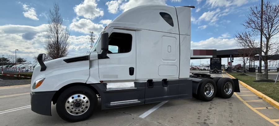
Freightliner Cascadia no communication with ECM is typically caused by a loss of ECM power, poor ground connections, damaged J1939 CAN bus wiring, faulty diagnostic connections, or a malfunctioning control module. These faults interrupt communication between the Engine Control Module (ECM) and other electronic systems, preventing diagnostic tools from retrieving engine data or fault codes. A communication failure does not automatically mean the ECM needs replacement.
Common symptoms include a no-start condition, intermittent engine communication, dashboard warning lights, and a diagnostic scanner that cannot establish a connection with the ECM. The exact symptoms depend on the truck’s model year, engine configuration, and electronic control architecture. For example, a damaged J1939 communication wire may prevent the ECM from exchanging data with the Common Powertrain Controller (CPC), while a blown ECM power fuse can prevent the module from operating altogether.
Diagnosing Freightliner Cascadia ECM communication problems requires checking power and ground circuits, verifying diagnostic connector operation, testing J1939 network integrity, and evaluating the ECM itself. Following this sequence helps identify the underlying fault before replacing expensive electronic components. This guide explains the causes, symptoms, diagnostic procedures, and repair solutions for restoring ECM communication on Freightliner Cascadia trucks.
What Causes No Communication With the ECM on a Freightliner Cascadia?
There are 6 main causes of ECM communication failure on a Freightliner Cascadia: loss of ECM power, poor ground connections, damaged J1939 wiring, faulty diagnostic connections, communication interference from other control modules, and internal ECM failure. Each fault can prevent the Engine Control Module from transmitting or receiving data, although the affected circuits and symptoms vary by truck model year and engine configuration.
Power supply and ground faults can prevent the ECM from operating, while J1939 network problems can interrupt communication even when the module receives the correct voltage. A diagnostic connector or scan tool problem can also create an apparent ECM communication failure without affecting normal engine operation. Identifying which condition is present is essential before replacing electronic components.
Can Power Supply or Ground Problems Prevent ECM Communication?
A blown ECM fuse, faulty power relay, damaged supply wire, or poor ground connection can prevent the Freightliner Cascadia ECM from communicating with diagnostic equipment and other control modules. The ECM requires stable electrical power and a reliable ground path to operate its processor and communication circuits. When either circuit fails, the module may stop responding to diagnostic requests.
ECM power supply problems can originate from corroded fuse terminals, loose electrical connectors, damaged wiring, or failed relays. For example, a fuse may appear intact during visual inspection but fail to deliver voltage because of corrosion or poor terminal contact. Similarly, a high-resistance ground connection can produce a voltage drop when the ECM draws current, even if a basic continuity test indicates that the ground circuit is connected.
Low battery voltage and unstable charging-system output can also interfere with electronic module operation. Technicians should verify ECM battery power, ignition-controlled power where applicable, and ground integrity using the wiring diagram for the specific vehicle. Measuring voltage under appropriate operating conditions is more reliable than relying on visual inspection alone.
Can J1939 Wiring or a Faulty Control Module Cause Communication Failure?
Damaged J1939 CAN bus wiring, defective network connections, incorrect termination, or a malfunctioning electronic control module can interrupt ECM communication on a Freightliner Cascadia. The SAE J1939 network allows the ECM to exchange engine operating information with other vehicle controllers. Communication depends on the integrity of the network wiring, electrical signaling, and connected modules.
J1939 wiring failures include open circuits, short circuits between CAN High and CAN Low, shorts to ground or power, and corroded connectors. The network also relies on terminating resistors to maintain signal integrity. A conventional J1939 CAN segment with two 120-ohm terminating resistors connected in parallel typically measures approximately 60 ohms between CAN High and CAN Low when tested under the correct power-off conditions. However, this measurement must be interpreted according to the specific network architecture and testing location.
A defective Common Powertrain Controller (CPC), gateway, or another connected module can also disrupt communication, depending on the Cascadia’s electronic architecture. For example, a module or wiring fault that holds a shared CAN circuit at an abnormal voltage can interfere with communication across that network segment. Technicians must distinguish a network-wide failure from a problem isolated to the ECM.
Diagnostic connector faults represent another possible cause. A damaged diagnostic port, missing connector power, poor ground, incompatible adapter, or incorrect diagnostic software configuration may prevent a scan tool from accessing the ECM even when the vehicle network is functioning.
Internal ECM failure is another possibility, but ECM replacement should only be considered after verifying its power supply, ground circuits, diagnostic access, and communication network. An ECM that remains unresponsive despite confirmed external electrical and network conditions may require further module-specific testing or replacement according to the manufacturer’s procedures.
What Are the Symptoms of Freightliner Cascadia ECM Communication Failure?
The 5 main symptoms of Freightliner Cascadia ECM communication failure are engine starting problems, diagnostic scanner connection failures, dashboard warning lights, missing engine data, and intermittent communication with electronic control modules. These symptoms occur when the Engine Control Module (ECM) cannot exchange information with other vehicle controllers or diagnostic equipment. Their severity depends on whether the communication failure affects the ECM itself, the J1939 network, or the diagnostic connection.
Engine starting problems are among the most noticeable symptoms. A Freightliner Cascadia may experience a no-crank condition, where the starter does not engage, or a crank-no-start condition, where the engine turns over but fails to start. Communication failures involving the ECM and Common Powertrain Controller (CPC) can interfere with engine control functions, depending on the vehicle configuration. However, starting problems can also result from battery, starter, fuel system, or other electrical faults, so they do not independently confirm ECM communication failure.
Diagnostic scanner connection failures occur when a diagnostic tool cannot establish communication with the ECM or retrieve engine-related diagnostic trouble codes. For example, Detroit DiagnosticLink may detect other electronic control modules while showing the ECM as unavailable. This pattern suggests that the diagnostic connection is functioning at least partially, but it does not establish whether the ECM, its power supply, or its network connection is defective. If the scanner cannot communicate with any module, the diagnostic connector, adapter, software configuration, and network power supply should also be investigated.
Dashboard warning lights and missing engine information can indicate disrupted communication between electronic control modules. Depending on the Cascadia’s model year and instrument cluster configuration, the driver may notice check engine warnings, electronic system alerts, or unavailable engine parameters. Missing engine speed, coolant temperature, or other ECM-supplied data can indicate that the instrument cluster or another controller is not receiving the expected messages. However, individual warning lights and missing readings must be interpreted alongside diagnostic trouble codes and network test results.
Intermittent ECM communication occurs when the diagnostic connection or vehicle network operates normally at one moment and fails at another. Loose connectors, corroded terminals, damaged wiring, and vibration-related electrical faults can cause this behavior. For example, a wiring harness with damaged conductors may temporarily lose electrical continuity when the engine moves or the truck travels over uneven pavement. Temperature changes and moisture intrusion can also affect compromised electrical connections.
These symptoms help technicians determine where to begin troubleshooting, but a confirmed ECM communication fault requires electrical and network testing rather than symptom identification alone. Comparing scanner access, module availability, power supply measurements, and J1939 communication status helps distinguish an ECM-specific failure from a broader vehicle electrical problem.
How Do You Diagnose No Communication With the ECM on a Freightliner Cascadia?
To diagnose no communication with the ECM on a Freightliner Cascadia, follow 6 steps: check battery voltage, verify ECM power and ground, inspect the diagnostic connector, test J1939 network resistance, check CAN wiring integrity, and evaluate ECM operation. This sequence helps distinguish electrical supply failures from communication network faults and internal module problems.
Begin by connecting a compatible heavy-duty diagnostic tool, such as Detroit DiagnosticLink with an appropriate vehicle communication adapter. Check whether the tool communicates with other electronic control modules. If multiple modules are unavailable, investigate the diagnostic connection and shared network before focusing on the ECM. Use the wiring diagram and service procedures corresponding to the truck’s VIN, model year, and engine configuration.
How Do You Check ECM Power and Ground Connections?
Check ECM power and ground connections by measuring battery supply voltage, verifying ignition-controlled power where applicable, and performing voltage-drop tests on the ground circuits. An ECM cannot communicate reliably without sufficient electrical power and a stable ground reference, even when its internal communication circuitry is functional.
Start by measuring battery voltage at the battery terminals and comparing it with the voltage available at the ECM power supply circuits. A fully charged 12-volt lead-acid battery typically measures approximately 12.6 volts at rest, although actual readings depend on battery condition, temperature, and recent charging activity. The ECM supply voltage should be evaluated against the manufacturer’s specifications under the appropriate operating conditions.
Inspect the ECM fuses and power relays using the vehicle-specific electrical diagram. Measure voltage on both sides of each applicable fuse rather than relying only on visual inspection. A fuse with voltage on its supply side but no voltage on its output side may be open. If voltage is missing from both sides, investigate the upstream power supply or relay circuit.
Next, test ECM ground connections by measuring voltage drop between the ECM ground terminal and the battery negative terminal while the circuit is carrying current. Excessive voltage drop indicates resistance in the ground path, potentially caused by corrosion, loose terminals, or damaged conductors. Use the manufacturer’s allowable voltage-drop limits rather than assuming one threshold applies to every circuit.
How Do You Test the J1939 CAN Bus?
Test the Freightliner Cascadia J1939 CAN bus by checking network resistance, inspecting CAN High and CAN Low wiring, and measuring communication signals with suitable diagnostic equipment. These tests identify termination problems, open circuits, short circuits, and abnormal network electrical conditions that can prevent ECM communication.
Begin with a resistance measurement between CAN High and CAN Low at the appropriate diagnostic connector or network test point. Perform this test only after switching off the ignition, isolating electrical power as required by the service procedure, and allowing connected modules to shut down. Resistance measurements on energized circuits can produce invalid readings or damage test equipment.
A conventional high-speed J1939 network segment containing two 120-ohm terminating resistors connected in parallel should measure approximately 60 ohms. A reading near 120 ohms can indicate a missing termination or an open circuit separating the measurement point from one terminating resistor. Very low resistance can suggest a short circuit or an additional unintended load. These interpretations apply only when the measured network segment uses the expected termination arrangement.
Inspect the twisted-pair CAN wiring for crushed insulation, exposed conductors, corroded terminals, and damage near the engine or chassis harness connections. Test for shorts between CAN High and CAN Low and for shorts to power or ground using the manufacturer’s procedures. Continuity measurements should be performed with the relevant circuits isolated to prevent misleading results.
A compatible oscilloscope can provide additional evidence by displaying CAN High and CAN Low signal activity. Abnormal signal levels, missing transitions, or distorted waveforms may indicate network faults. However, electrical activity alone does not confirm that the ECM is transmitting valid J1939 messages. Compare waveform observations with diagnostic tool results and the vehicle-specific network layout.
How Do You Determine Whether the ECM Is Faulty?
Determine whether the Freightliner Cascadia ECM is faulty by confirming correct power and ground conditions, verifying network integrity, and ruling out diagnostic equipment or communication gateway problems. An ECM that remains inaccessible after these checks may have an internal failure, but lack of communication alone is insufficient evidence for replacement.
First, confirm that the diagnostic adapter and software are compatible with the truck’s electronic architecture. Verify diagnostic connector power, ground, and communication access. If the scanner communicates with the CPC, ACM, or other available controllers but not the ECM, investigate the ECM’s individual network branch and electrical supply circuits.
Next, compare the ECM communication status with information reported by other controllers. Communication-related diagnostic trouble codes can help identify which modules have stopped receiving expected ECM messages. These codes must be interpreted according to their source module, occurrence conditions, and the manufacturer’s diagnostic instructions.
Inspect the ECM connectors for moisture intrusion, corrosion, damaged pins, and loose terminal retention. A connector defect can interrupt ECM power or communication without requiring replacement of the module. For example, a corroded CAN terminal may prevent diagnostic access while the ECM itself remains operational.
ECM replacement becomes a justified repair option only when module-specific testing supports an internal failure and external circuit faults have been excluded. Replacement units must match the vehicle’s hardware requirements and may require programming, parameter configuration, or other manufacturer-specified procedures before normal communication and engine operation can be restored.
How Do You Fix Freightliner Cascadia ECM Communication Problems?
To fix Freightliner Cascadia ECM communication problems, repair the confirmed electrical or network fault, restore damaged connections, or replace a defective control module when testing establishes an internal failure. The correct repair depends on whether the problem originates from the ECM power supply, ground circuit, J1939 wiring, diagnostic connection, or electronic control hardware.
Start with the fault identified during diagnosis rather than replacing components based on symptoms alone. For example, a truck with missing ECM battery voltage requires power circuit repair, while a vehicle with correct ECM power and ground but abnormal J1939 resistance requires network troubleshooting. After completing repairs, verify communication with a compatible diagnostic tool, check for remaining active faults, and confirm normal engine operation.
How Do You Repair ECM Power, Ground, and Wiring Problems?
Repair ECM power and ground problems by replacing failed electrical components, restoring damaged conductors, and correcting loose or corroded connections. These repairs restore the stable electrical supply required for ECM operation and communication with other vehicle controllers.
Replace a blown ECM fuse only after identifying the condition that caused it to fail. A shorted supply wire or damaged component can cause a replacement fuse to blow again. If a power relay fails to deliver the required voltage, inspect its control circuit and terminal connections before installing a replacement. Repair damaged power wires using the conductor size, terminal type, and connection method specified for the vehicle.
Ground circuit repairs involve removing corrosion, securing loose connections, and replacing damaged terminals or conductors. Clean affected grounding surfaces using an appropriate method and restore protective coatings where required. After completing the repair, repeat the voltage-drop test under load to confirm that excessive resistance has been eliminated.
Repair damaged J1939 wiring by restoring the original twisted-pair configuration, maintaining correct network connections, and replacing defective connectors or terminals. CAN communication depends on controlled electrical characteristics, so improper splices, excessive untwisted wire length, or unsuitable replacement conductors can introduce signal problems. Follow Freightliner or Detroit service specifications for approved wiring repairs rather than using generic electrical splicing methods.
For example, a J1939 harness damaged by rubbing against a metal bracket may have exposed conductors that intermittently short to ground. Repairing the affected wiring, restoring insulation, and securing the harness away from the contact point addresses both the communication failure and its underlying cause. Afterward, verify network resistance under the specified test conditions and confirm that the diagnostic scanner can communicate with the ECM.
How Do You Restore Communication After Replacing a Faulty ECM?
Restore communication after ECM replacement by installing a compatible module, completing the required programming and configuration, and verifying communication with the vehicle’s electronic control network. Replacing the physical ECM does not guarantee normal operation because the replacement module must support the truck’s engine, hardware configuration, and control system requirements.
Before installation, verify the replacement ECM part number and compatibility using the vehicle identification number, engine serial number, and applicable manufacturer service information. A module intended for a different engine or electronic architecture may not communicate correctly or support the required engine functions.
ECM replacement may require programming with Detroit DiagnosticLink or other manufacturer-approved service equipment, depending on the module and vehicle configuration. Required operations can include loading compatible software, restoring vehicle-specific parameters, and completing applicable configuration procedures. Programming must be performed with a stable electrical power supply to reduce the risk of interruption.
After installation and programming, reconnect the diagnostic equipment and confirm that the ECM is recognized. Check communication with related controllers, retrieve diagnostic trouble codes, and resolve any remaining active faults. Verify that the ECM reports expected engine parameters, including engine speed and coolant temperature, when the relevant operating conditions are met.
Finally, perform the manufacturer-required functional checks and confirm normal engine starting and operation. A successful ECM communication repair restores diagnostic access, resolves the original communication fault, and allows the affected electronic systems to exchange the required data. If communication remains unavailable, repeat the relevant power, ground, network, and configuration checks before concluding that the replacement ECM is defective.
How Can You Tell if a Freightliner Cascadia ECM Needs Replacement?
A Freightliner Cascadia ECM may need replacement when it fails to communicate despite verified power, ground, J1939 network integrity, and properly functioning diagnostic equipment. These findings raise suspicion of an internal ECM failure, but a replacement decision should be supported by manufacturer-specific diagnostic procedures rather than communication loss alone.
There are 4 key indicators of a potentially defective ECM: persistent communication failure, verified electrical supply conditions, confirmed network functionality, and evidence of internal module damage or malfunction. For example, an ECM that receives the specified battery and ignition power, has reliable ground connections, and remains inaccessible through a verified communication path may have an internal processor or communication circuit fault. However, technicians must also exclude connector damage, incompatible diagnostic software, and faults in intermediate communication modules.
A faulty ECM must also be distinguished from a defective Common Powertrain Controller (CPC) or communication gateway. These controllers perform different functions within the Freightliner Cascadia electronic architecture. Depending on the model year and network configuration, a CPC or gateway problem can interrupt access to engine information without indicating that the ECM hardware has failed. Comparing module communication status, network measurements, and diagnostic trouble codes helps isolate the affected component.
Physical damage provides additional diagnostic evidence. Water intrusion, severe connector corrosion, damaged terminals, or visible heat damage may indicate conditions that have affected ECM operation. However, external damage does not automatically confirm internal electronic failure. For example, corrosion limited to an ECM connector may be repairable without replacing the module. The affected circuits must be inspected and tested before making a replacement decision.
ECM replacement requires verification of hardware compatibility and any necessary software programming. The replacement module must match the truck’s engine configuration and applicable manufacturer requirements. Depending on the system, installation may require software updates, parameter configuration, or other service procedures using approved diagnostic equipment. A replacement ECM that is incorrectly configured may remain inaccessible or prevent normal engine operation.
The most reliable replacement decision comes from completing the applicable Freightliner or Detroit diagnostic procedure and documenting the test results. Replacing an ECM without confirming the root cause risks unnecessary expense and may leave the original communication problem unresolved.
Read more: Freightliner Cascadia No Power to Dash: Causes & Fixes
How Much Does It Cost to Fix Freightliner Cascadia ECM Communication Failure?
The cost to fix Freightliner Cascadia ECM communication failure depends on the underlying fault, diagnostic labor, replacement parts, and required programming. Repairing a corroded connector or damaged ground connection generally involves less work than replacing an ECM and configuring it for the vehicle. An accurate estimate requires identifying the failed circuit or component before calculating repair expenses.
There are 4 main repair cost categories: electrical diagnosis, power and ground circuit repair, J1939 network repair, and ECM replacement. Diagnostic charges depend on the time required to locate the fault and the equipment used, including Detroit DiagnosticLink, a compatible vehicle communication adapter, and electrical testing instruments. Intermittent faults generally require additional testing because the failure may not be present during the initial inspection.
Power supply and ground repairs typically involve fuses, relays, wiring, terminals, or electrical connectors. Replacing an accessible fuse or repairing a loose ground connection requires fewer labor operations than tracing a damaged power wire through a large engine or chassis harness. For example, a corroded ECM ground terminal may only require connector service, while a shorted wire inside a protected harness may require extensive disassembly and circuit testing.
J1939 communication repairs vary according to the location and extent of the wiring damage. Repairing an accessible connector differs from locating an intermittent open circuit inside a long harness. Network faults involving multiple controllers may also increase diagnostic labor because technicians must isolate the affected network segment and verify communication after the repair.
ECM replacement is generally the most expensive repair category because it combines module hardware costs with installation, programming, and verification. The total depends on the engine configuration, ECM part number, availability of compatible replacement units, and manufacturer-specific programming requirements. New, remanufactured, and used modules may have different purchase costs, warranty conditions, and compatibility requirements.
For an accurate repair estimate, request an itemized quote covering diagnostic labor, replacement parts, wiring repairs, programming, and final system testing. Compare the estimate with the confirmed diagnostic findings rather than authorizing ECM replacement solely because a scanner reports no communication. This approach helps prevent unnecessary component replacement and ensures the repair addresses the actual failure.
How Can You Prevent ECM Communication Problems on a Freightliner Cascadia?
Prevent Freightliner Cascadia ECM communication problems by maintaining battery and charging system health, protecting J1939 wiring, inspecting electrical connectors, and keeping ECM ground connections secure. These preventive measures reduce the risk of voltage instability, corrosion, open circuits, and intermittent network failures that can interrupt communication between electronic control modules.
Battery and charging system maintenance helps maintain a stable electrical supply for the ECM and other vehicle controllers. Inspect battery terminals for corrosion, verify that cable connections are secure, and test battery condition during scheduled maintenance. Check alternator output and charging system performance against the manufacturer’s specifications. For example, a loose battery terminal can create intermittent voltage drops that disrupt electronic module operation, particularly during engine starting or periods of high electrical demand.
J1939 wiring harness protection reduces communication failures caused by vibration, abrasion, heat, and moisture. Inspect harness routing near the engine, frame rails, mounting brackets, and other areas exposed to mechanical movement. Look for damaged insulation, loose retaining clips, and wiring that contacts sharp edges or hot components. Secure affected harnesses using approved mounting methods while preserving the original twisted-pair configuration of CAN communication wires.
Electrical connector maintenance helps prevent corrosion and poor terminal contact. Inspect accessible ECM, CPC, and network connectors for damaged seals, moisture intrusion, bent pins, and loose terminal retention. For example, a deteriorated connector seal can allow water to reach electrical terminals, increasing resistance and eventually interrupting communication. Repair damaged seals and terminals using manufacturer-approved components and procedures. Avoid applying unapproved chemicals or lubricants to electronic connectors.
Ground connection inspection helps prevent voltage drops that interfere with ECM operation. Check applicable engine, chassis, and module grounding points for corrosion, loose fasteners, and damaged conductors. Restore defective connections according to Freightliner service specifications and verify electrical integrity after repairs.
Preventive maintenance should also include reviewing communication-related diagnostic trouble codes when the truck undergoes scheduled service. Intermittent network faults may appear in stored diagnostic records before a complete communication failure develops. Investigating recurring faults, especially those associated with voltage supply or J1939 communication, helps identify deteriorating electrical connections before they cause more extensive problems.
Consistent electrical maintenance reduces preventable ECM communication failures but cannot eliminate internal electronic component defects. When communication problems recur, technicians should perform a complete diagnostic evaluation rather than repeatedly clearing fault codes or replacing components without confirming the cause. For additional network diagnostic procedures, see a dedicated guide to J1939 communication troubleshooting on Freightliner Cascadia trucks.