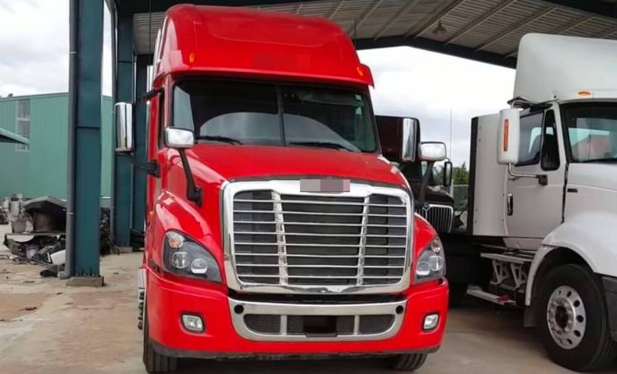
The ATS electrical system on a Freightliner is the electrical and electronic control portion of the truck’s aftertreatment system, which monitors and manages components responsible for controlling diesel exhaust emissions. ATS stands for aftertreatment system. It works with sensors, wiring harnesses, electrical connectors, control modules, and emissions-related components such as the diesel particulate filter (DPF), selective catalytic reduction (SCR) system, and diesel exhaust fluid (DEF) system.
An ATS electrical system problem occurs when the system detects an abnormal electrical signal, circuit condition, sensor reading, or related aftertreatment fault. Depending on the specific failure, a Freightliner may display an ATS or emissions warning, store diagnostic trouble codes, experience regeneration problems, or eventually enter an engine derate condition. An ATS warning therefore does not automatically mean that the DPF, DEF system, or a specific sensor needs replacement; the underlying fault must first be identified.
Diagnosing the problem requires determining which circuit or component triggered the warning and then checking its fault codes, wiring, connectors, power supply, grounds, sensors, and related aftertreatment components. This guide explains how the Freightliner ATS electrical system works, its main components, common symptoms and causes, diagnostic steps, repair options, and whether a truck can continue operating when an ATS electrical warning appears.
What Is the ATS Electrical System on a Freightliner?
The ATS electrical system on a Freightliner is the electrical control network that monitors and supports the truck’s diesel aftertreatment system. ATS stands for aftertreatment system, which handles exhaust after it leaves the engine to reduce regulated emissions. The electrical side connects sensors, wiring, connectors, power and ground circuits, and electronic controls with aftertreatment components such as the diesel particulate filter (DPF), selective catalytic reduction (SCR) system, and diesel exhaust fluid (DEF) system.
The ATS electrical system provides the electronic information required to determine whether the aftertreatment process is operating correctly. Sensors measure conditions such as exhaust temperature, NOx levels, DPF pressure differential, and other system parameters. These measurements are converted into electrical signals that the truck’s electronic controls use to monitor exhaust treatment and identify abnormal operating conditions. For example, an exhaust temperature sensor provides data needed to determine whether temperatures are within the expected range during an active regeneration event.
An ATS electrical fault therefore does not identify one specific failed part. The fault can originate from a sensor, damaged wire, corroded connector, poor power or ground connection, or another component involved in aftertreatment monitoring and control. A problem elsewhere in the aftertreatment system can also generate related diagnostic information. This is why replacing a sensor simply because its name appears in a diagnostic trouble code can result in an incorrect repair.
The exact ATS configuration also depends on the Freightliner model, engine, emissions configuration, and model year. Component locations, diagnostic procedures, wiring arrangements, and available fault codes are not identical across every Freightliner truck. The vehicle and engine configuration should therefore be identified before using a wiring diagram, testing a circuit, or replacing an ATS component.
How Does the Freightliner ATS Electrical System Work?
The Freightliner ATS electrical system works by collecting sensor data, transmitting electrical signals to electronic controls, evaluating operating conditions, and commanding or monitoring the appropriate aftertreatment response. The basic process can be represented as sensor input → electrical signal → electronic control → system response → diagnostic feedback.
Sensors provide the input. An exhaust temperature sensor, for example, monitors temperature at a specific point in the exhaust system. A differential pressure sensor measures pressure conditions associated with the DPF, while NOx sensors provide information related to nitrogen oxide levels. Wiring harnesses and connectors carry these signals between the sensors and electronic controls. Stable power and ground circuits are necessary because an otherwise functional sensor cannot provide reliable information when its electrical supply or circuit is compromised.
Electronic controls evaluate these inputs against expected operating conditions. When the signals are valid, the system can use them to monitor functions such as DPF regeneration and SCR operation. When a signal is missing, outside an expected range, electrically implausible, or associated with another detected malfunction, the diagnostic system can store a fault code and trigger a dashboard warning.
This diagnostic feedback is important because one visible ATS warning can have different underlying causes. For example, an abnormal sensor reading may result from a failed sensor, but damaged wiring or a poor connector can produce a similar signal problem. Diagnosis therefore needs to establish whether the problem originates at the component itself, its electrical circuit, or another part of the aftertreatment system before a repair is made.
What Components Are Part of the Freightliner ATS Electrical System?
The Freightliner ATS electrical system includes sensors, wiring harnesses, connectors, power and ground circuits, electronic controls, and the electrical interfaces used by related aftertreatment components. These parts operate as a network rather than as independent components. A failure at one point in the network can affect the information available to the rest of the system.
Sensors form the measurement layer of the system. Important examples include NOx sensors, exhaust temperature sensors, DPF differential pressure sensors, and sensors associated with DEF and SCR operation. Each sensor monitors a specific condition and supplies information that helps the electronic controls determine whether the aftertreatment system is functioning within its expected parameters. A failed or unreliable sensor can therefore create a diagnostic fault even when the mechanical portion of the monitored component remains functional.
Wiring harnesses and electrical connectors provide the communication paths between these components. They carry sensor signals, power, ground, and other electrical information through an environment exposed to heat, vibration, moisture, road contamination, and repeated thermal cycles. Damage to insulation, an open or shorted circuit, a loose terminal, or corrosion inside a connector can interrupt these paths and produce an ATS electrical fault.
Power and ground circuits are equally important because sensors and electronic controls require the correct electrical supply to operate reliably. Low voltage, excessive resistance, a poor ground, or a circuit protection problem can affect multiple components and create symptoms that resemble individual sensor failures. Checking circuit integrity can therefore prevent unnecessary component replacement.
The electrical system ultimately interacts with physical aftertreatment components such as the DPF, SCR system, and DEF system. These components perform different emissions-control functions, while sensors and electronic controls monitor their operation. This relationship explains why a DPF, SCR, or DEF-related problem may appear within the broader ATS diagnostic context even though an ATS electrical fault and a mechanical aftertreatment failure are not automatically the same problem.
What Are the Symptoms of a Freightliner ATS Electrical System Problem?
The main symptoms of a Freightliner ATS electrical system problem are dashboard warnings, diagnostic trouble codes, regeneration problems, reduced engine performance, and engine derate. The exact symptoms depend on which sensor, circuit, connector, control function, or related aftertreatment component is affected. An electrical fault may initially produce only a warning, while a persistent problem can interfere with emissions-system operation and lead to more noticeable performance restrictions.
A dashboard warning or check-engine light is often the first visible indication of an ATS problem. The truck’s diagnostic system monitors electrical signals from aftertreatment sensors and related circuits. When a signal falls outside its expected range, disappears, or becomes electrically implausible, the system can store a diagnostic trouble code and activate a warning. The warning identifies the presence of a detected problem, but it does not by itself identify the component that must be replaced.
Regeneration problems can also occur when the system cannot obtain reliable information from components needed to monitor the process. DPF regeneration requires the truck to evaluate conditions within the exhaust and aftertreatment system. If an exhaust temperature, differential pressure, or related electrical signal is unreliable, the control system may be unable to manage or verify regeneration as expected. Repeated regeneration problems therefore require diagnosis of both the aftertreatment components and their electrical circuits.
Engine derate is one of the more serious possible consequences of an unresolved ATS-related fault. A derate reduces available engine performance when the control system determines that certain operating or emissions conditions require a protective response. However, an ATS warning does not mean the truck will automatically derate. The result depends on the fault, its severity, how long it remains active, and the specific engine and aftertreatment configuration.
Multiple symptoms occurring together provide stronger diagnostic context than one warning alone. For example, an emissions warning accompanied by an active fault code and repeated regeneration failure provides more useful information than an isolated dashboard message. The correct next step is to retrieve the stored codes and diagnose the affected system rather than replacing a DPF, sensor, or DEF-related component based only on the visible warning.
What Causes ATS Electrical System Problems on a Freightliner?
There are 7 main groups of causes of Freightliner ATS electrical system problems: sensor failure, damaged wiring, connector problems, power-supply faults, poor grounds, fuse or control-circuit faults, and problems involving related aftertreatment components. Identifying the correct group matters because several different failures can produce similar warning messages and diagnostic symptoms.
A failed or unreliable sensor is one possible cause. Aftertreatment sensors operate in demanding conditions and provide measurements used to monitor exhaust-system performance. Examples include NOx sensors, exhaust temperature sensors, DPF differential pressure sensors, and DEF-related sensors. A sensor that produces an incorrect, intermittent, or missing signal can cause the diagnostic system to identify an abnormal condition and store a corresponding fault.
Damaged wiring is another major source of electrical problems. ATS wiring is exposed to vibration, heat, moisture, debris, and environmental contamination during vehicle operation. A wire can develop damaged insulation, excessive resistance, an open circuit, or a short circuit. For example, wiring damaged near a high-temperature exhaust component may interrupt a sensor circuit even though the sensor itself remains functional.
Loose, damaged, or corroded electrical connectors can create similar symptoms. A connector provides the electrical interface between the wiring harness and a sensor or other component. Corrosion can increase electrical resistance, while a loose or damaged terminal can produce an intermittent connection. The resulting signal may appear and disappear as the truck vibrates, making an intermittent connector fault harder to identify than a complete circuit failure.
Power-supply and ground problems can affect one or several ATS-related circuits. A component needs the correct power supply and a reliable ground before its output can be evaluated accurately. Low system voltage, excessive circuit resistance, or a poor ground connection can create abnormal readings or communication problems. For this reason, electrical diagnosis should verify power and ground integrity before concluding that an expensive sensor or control component has failed.
Fuse, relay, or control-circuit problems can also interrupt power or prevent an electrical function from operating correctly where those components are used in the applicable circuit. The exact circuit arrangement varies by Freightliner model, engine, model year, and emissions configuration. The correct wiring information for the specific vehicle should therefore be used when identifying circuit protection, terminals, power sources, and grounds.
The final group includes faults involving related aftertreatment components or processes. A DPF, SCR, or DEF-system problem can generate diagnostic information within the broader ATS context because the electrical controls continuously monitor aftertreatment operation. This does not mean every DPF or DEF problem is an electrical failure. Instead, the diagnostic process must determine whether the abnormal condition originates from the physical aftertreatment component, the sensor monitoring it, or the electrical circuit carrying the sensor information.
The relationship between these causes explains why parts replacement should follow diagnosis rather than precede it. A code associated with a NOx sensor, for example, can direct attention toward that sensor and its circuit, but the complete diagnostic path may also require checking its connector, wiring, power supply, ground, and relevant operating data. Confirming the failure mechanism reduces the risk of replacing a functional component while leaving the actual electrical fault unresolved.
How Do You Diagnose an ATS Electrical System Problem on a Freightliner?
Diagnose a Freightliner ATS electrical system problem by identifying the warning, retrieving the diagnostic trouble codes, inspecting the affected components, checking wiring and connectors, verifying power and ground, evaluating sensor data, and confirming the failed circuit or component. The purpose of this sequence is to identify the actual failure instead of replacing the component mentioned in a fault code without testing it.
Start with the warning displayed by the truck and any changes in vehicle operation. Record whether the truck has a check-engine or emissions warning, regeneration problem, reduced engine performance, or active derate. These symptoms establish the diagnostic context. A truck displaying only an ATS-related warning requires a different level of urgency from one experiencing repeated regeneration failure and an active engine derate.
The next step is to connect a compatible diagnostic scanner and retrieve active and stored diagnostic trouble codes. Record the complete code information before clearing anything. Fault status, related codes, and available operating data can help determine whether the problem is currently active, intermittent, or connected to another aftertreatment fault. Clearing codes before recording this information can remove useful evidence without repairing the underlying problem.
Inspect the component and its electrical circuit after identifying the affected area. Check the wiring harness for damaged insulation, rubbing, heat exposure, broken wires, or other visible damage. Inspect electrical connectors for loose terminals, corrosion, moisture, contamination, and signs of overheating. A damaged connector or wire can alter a sensor signal enough to produce a fault even when the sensor itself is functional.
Verify power and ground before condemning an ATS sensor or other electrical component. A component cannot produce reliable information without the electrical conditions required for normal operation. Depending on the circuit and diagnostic procedure, testing may involve checking supply voltage, ground integrity, continuity, resistance, or signal behavior. The correct specifications and test points depend on the Freightliner model, engine, model year, and aftertreatment configuration, so vehicle-specific service information should be used.
Sensor data should then be compared with expected operating conditions. A reading that is missing, fixed, implausible, or inconsistent with related sensor data can help narrow the problem. However, an abnormal value does not automatically prove the sensor has failed. The same result can occur when wiring resistance, connector damage, loss of power, poor ground, or another system condition affects the signal.
The diagnosis is complete only when the failure mechanism has been confirmed. For example, finding a fault associated with an exhaust temperature sensor is the beginning of the diagnostic process. Confirming that the sensor receives the correct electrical supply and has intact wiring but still produces an invalid output provides substantially stronger evidence that the sensor itself is faulty. This sequence prevents unnecessary parts replacement and makes the repair directly address the cause of the ATS warning.
How Do You Read Freightliner ATS Fault Codes?
Read Freightliner ATS fault codes by retrieving the complete diagnostic code with a compatible scan tool and interpreting it in the context of the specific engine, aftertreatment system, and vehicle configuration. A fault code indicates where the diagnostic system detected an abnormal condition; it does not always identify the part that needs replacement.
Heavy-duty truck diagnostics can use information such as SPN and FMI to describe the affected parameter and the type of detected failure. The complete diagnostic information matters because two faults involving the same sensor or system can represent different electrical conditions. For example, the diagnostic direction for a circuit with an abnormal voltage condition can differ from the direction for a signal that is present but outside its expected operating range.
Related codes should also be evaluated together. Several ATS codes appearing at the same time can share one underlying cause, particularly when multiple circuits depend on the same power supply, ground, connector, wiring section, or system condition. Treating every stored code as a separate failed component can lead to unnecessary repairs.
Use the code to establish a testing path rather than a replacement instruction. The practical sequence is code identification → circuit identification → visual inspection → power and ground verification → wiring and connector testing → component testing → repair confirmation. If the code points toward a sensor circuit, inspect and test that circuit before replacing the sensor.
Fault-code interpretation must also match the truck’s actual configuration. Freightliner trucks can use different engines, emissions systems, electrical layouts, and diagnostic procedures across models and model years. A code description or repair procedure from a different configuration should not be assumed to apply to the truck being diagnosed.
After repairing the confirmed fault, clear codes when the applicable diagnostic procedure calls for it and verify that the problem does not return. Verification may include checking live data, operating the engine under required conditions, completing an appropriate drive or regeneration procedure, or rescanning the vehicle. A successful repair corrects the condition that generated the ATS fault; simply clearing the code only removes the stored diagnostic information.
How Do You Fix an ATS Electrical System Problem on a Freightliner?
Fix a Freightliner ATS electrical system problem by repairing the specific circuit, connection, sensor, or component confirmed as faulty during diagnosis. There is no single repair that applies to every ATS warning because similar symptoms can result from damaged wiring, connector problems, inadequate power or ground, sensor failure, or a related aftertreatment fault. The repair should therefore address the verified failure rather than the dashboard warning alone.
Repair damaged wiring when testing identifies an open circuit, short circuit, excessive resistance, damaged insulation, or another wiring defect. The repaired circuit must restore reliable electrical continuity and remain protected from heat, vibration, moisture, and abrasion. Simply moving a damaged harness or temporarily restoring contact can make an intermittent fault disappear without correcting the underlying wiring problem.
Repair connector problems when loose terminals, corrosion, contamination, moisture, or physical damage interfere with the electrical connection. Connector faults are especially important when a warning appears intermittently because vibration and temperature changes can repeatedly interrupt a marginal connection. The connector and terminals should be inspected together because replacing a sensor while retaining a damaged connector can cause the same ATS fault to return.
Correct power and ground faults before replacing sensors or electronic components. A low or unstable supply voltage can prevent a functional component from operating correctly, while excessive resistance in a ground circuit can distort electrical behavior. For example, replacing a sensor will not correct a warning caused by a damaged power-supply wire feeding that sensor. Verification of the circuit therefore needs to be part of the repair, not just the initial diagnosis.
Replace a sensor only after the diagnostic process confirms that the sensor itself has failed. ATS-related sensors can include exhaust temperature, NOx, DPF differential pressure, and DEF-related sensors. The exact replacement and verification procedure depends on the Freightliner model, engine, model year, and emissions configuration. Vehicle-specific service information should be followed when a repair requires component installation, calibration, initialization, or another prescribed procedure.
A related DPF, SCR, or DEF problem requires repair of that specific aftertreatment condition rather than treatment as a generic electrical failure. For example, a regeneration problem can exist alongside an electrical fault, but correcting the electrical circuit does not automatically resolve every physical condition affecting the DPF. Diagnostic information should establish how the faults are related before multiple components are replaced.
The final step is repair verification. Rescan the truck, check whether the relevant fault remains active, and confirm that the repaired circuit or component now operates correctly. Depending on the fault and manufacturer procedure, verification may also involve reviewing live data or confirming proper operation during an applicable regeneration or operating cycle. The ATS repair is complete when the cause of the fault has been corrected and the system verifies normal operation, not merely when the dashboard warning disappears.
Can You Reset a Freightliner ATS Electrical Warning?
An ATS electrical warning can be cleared when the underlying fault has been repaired and the applicable diagnostic procedure allows the code to be cleared, but resetting the warning does not fix the problem that caused it. This distinction is important because clearing diagnostic information and repairing an electrical fault are two separate actions.
A compatible diagnostic tool can be used to clear certain stored fault information after diagnosis and repair. Some conditions may also require specific verification or operating procedures before the system recognizes that the fault is no longer present. The exact process depends on the engine, control system, fault type, and vehicle configuration.
Clearing a code before repairing its cause provides no permanent solution. For example, if damaged wiring creates an intermittent sensor circuit, clearing the fault may temporarily remove the warning while the electrical defect remains. When the circuit fails again and the diagnostic criteria are met, the control system can detect the condition again and the warning can return.
Repeatedly clearing ATS codes can also make diagnosis more difficult because stored fault information provides useful evidence about when and how the problem occurred. Record active and stored diagnostic information before clearing codes, especially when the fault is intermittent or several related codes are present.
Repair first and reset second. Confirm the failed circuit or component, perform the required repair, clear the applicable codes according to the correct diagnostic procedure, and then verify that the fault does not return. If the warning reappears, further diagnosis is required rather than repeated resetting.
Can You Drive a Freightliner With an ATS Electrical System Warning?
You may be able to drive a Freightliner with an ATS electrical system warning when the fault is non-critical and the truck operates normally, but continued driving depends on the specific fault, warning severity, and whether an engine derate or other serious symptom is active. An ATS warning should not be ignored because a minor electrical problem can interfere with aftertreatment monitoring and may progress into a more restrictive fault if the underlying cause remains unresolved.
Start by checking the dashboard for additional warnings and changes in vehicle behavior. An isolated ATS or emissions warning without noticeable performance changes does not provide enough information to determine the severity of the problem. Retrieve the diagnostic trouble codes as soon as practical because the codes provide a more specific diagnostic direction than the warning light alone.
Continued driving becomes more concerning when the ATS warning occurs with reduced engine power, an active derate, repeated regeneration failure, abnormal engine behavior, or additional critical warnings. These symptoms indicate that the problem is affecting more than a stored diagnostic message. Continuing normal operation without identifying the fault can allow an unresolved aftertreatment condition to become more difficult or expensive to repair.
Regeneration problems also require attention because the DPF depends on proper operating conditions and reliable sensor information for the system to monitor regeneration. An electrical fault affecting an exhaust temperature sensor, differential pressure sensor, wiring circuit, or related input can interfere with this process. Repeatedly attempting regeneration without diagnosing the electrical problem does not address the underlying cause.
The correct response is therefore based on fault severity rather than the ATS warning alone. Retrieve the fault codes and diagnose the truck promptly if it continues to operate normally; seek professional diagnosis before continued operation when the warning is accompanied by an active derate, persistent regeneration problems, significant power loss, or other serious operating symptoms. The applicable Freightliner and engine service information should take priority when the vehicle displays a warning that requires a specific operator response.
How Can You Prevent Freightliner ATS Electrical Problems?
Prevent Freightliner ATS electrical problems by maintaining wiring and connectors, correcting electrical faults early, keeping the truck’s power and ground circuits in good condition, and maintaining the related aftertreatment system according to the applicable service requirements. Preventive maintenance cannot eliminate every sensor or component failure, but it can reduce faults caused by damaged connections, deteriorated wiring, and unresolved system problems.
Inspect ATS-related wiring during routine maintenance, especially in areas exposed to exhaust heat, vibration, road debris, or abrasion. Look for damaged insulation, loose harness routing, rubbing points, heat damage, and previous repairs that are deteriorating. Finding a damaged wire before the circuit becomes open or shorted can prevent an intermittent fault from developing into a persistent ATS warning.
Electrical connectors should also remain secure, clean, and protected from conditions that can compromise terminal contact. Moisture, contamination, corrosion, loose terminals, and damaged connector housings can increase resistance or interrupt a sensor signal. For example, a functional sensor connected through corroded terminals can produce unreliable data even though replacing the sensor itself would not correct the connection problem.
Maintain the truck’s broader electrical system because ATS sensors and controls depend on stable power and ground. Battery, charging, power-distribution, and ground problems should be corrected when identified. A voltage or ground problem that affects several circuits can create multiple diagnostic symptoms, making the original fault harder to isolate if it is allowed to persist.
Address recurring fault codes instead of repeatedly clearing them. A warning that disappears after codes are cleared but later returns indicates that the condition may still exist or has occurred again. Recording the code information and diagnosing the affected circuit preserves useful evidence and allows the underlying failure to be repaired before it creates additional operating problems.
Related aftertreatment maintenance is also important. The electrical system monitors physical processes involving components such as the DPF, SCR system, and DEF system, so problems in these areas can produce ATS-related diagnostic information. Preventive maintenance works best when electrical circuits and the aftertreatment components they monitor are treated as connected parts of the same emissions-control system.
What Is the Difference Between an ATS Electrical Fault and a DPF Problem?
An ATS electrical fault involves the electrical or electronic monitoring and control of the aftertreatment system, while a DPF problem involves the diesel particulate filter or the processes required for the filter to operate correctly. The two problems can be related, but they should not be treated as interchangeable diagnoses.
The diesel particulate filter captures particulate matter from diesel exhaust. As soot accumulates, the aftertreatment system uses regeneration to reduce the accumulated material under the required operating conditions. Sensors and electrical circuits provide information that allows the electronic controls to monitor this process. The DPF is therefore a physical aftertreatment component, while the ATS electrical system provides part of the monitoring and control network surrounding it.
An ATS electrical fault can affect DPF operation without the filter itself being the original cause. For example, a problem involving a differential pressure sensor, exhaust temperature sensor, connector, or associated wiring can provide unreliable information about conditions around the DPF. The control system may then store diagnostic trouble codes or have difficulty verifying that an expected aftertreatment process is occurring correctly.
A DPF problem can also exist without the primary failure being electrical. Conditions involving excessive soot accumulation, regeneration difficulties, or a physical filter-related problem require diagnosis of the DPF and the processes affecting it. Replacing an electrical component will not correct a physical DPF condition unless that electrical component is confirmed as the cause of the problem.
The distinction becomes important when an ATS warning and a DPF-related symptom occur together. A DPF-related code does not automatically mean the DPF needs replacement, and an ATS electrical warning does not automatically mean the problem is inside the filter. Diagnosis should determine whether the fault originates from the DPF, a sensor monitoring it, the electrical circuit connected to that sensor, or another condition affecting regeneration.
For example, a truck with repeated regeneration problems and a differential-pressure-related fault requires more than one assumption about the DPF. The diagnostic process should evaluate the fault information, sensor data, wiring and connectors, and the relevant DPF condition. This separates an electrical measurement problem from an actual aftertreatment problem and reduces unnecessary parts replacement.
Read more: Freightliner Stop Engine Light: Causes & What to Do
What Is the Difference Between an ATS Electrical Fault and a DEF System Problem?
An ATS electrical fault is a broader electrical or electronic problem within the aftertreatment system, while a DEF system problem specifically involves the components and processes associated with diesel exhaust fluid and SCR operation. A DEF-related electrical fault can fall within the broader ATS diagnostic context, but not every ATS electrical problem originates in the DEF system.
Diesel exhaust fluid is used as part of the selective catalytic reduction process to help control nitrogen oxide emissions. The DEF system includes components that store, deliver, monitor, and manage the fluid as required by the applicable emissions configuration. Electrical sensors and controls provide information needed to monitor these functions and determine whether the system is operating as expected.
A DEF problem can therefore have either an electrical or non-electrical diagnostic cause. A sensor circuit, damaged connector, wiring fault, or electrical supply problem can interfere with DEF-system monitoring. Other DEF-related conditions can involve the fluid-delivery system or another physical part of the SCR and DEF process. The presence of a DEF warning alone does not establish which type of failure has occurred.
The broader ATS electrical system also monitors components outside the DEF system. Exhaust temperature sensors, DPF-related sensors, NOx sensors, wiring circuits, power and ground connections, and other aftertreatment controls can produce ATS-related faults without a DEF-system failure. This is why treating every ATS warning as a DEF problem can send the diagnostic process in the wrong direction.
Diagnostic trouble codes provide the starting point for separating the two conditions. When the code identifies a DEF-related circuit or parameter, diagnose that specific component and its electrical circuit; when the code identifies another ATS area, follow the diagnostic path for that system instead. Related codes should be evaluated together because one underlying electrical or aftertreatment condition can generate more than one diagnostic symptom.
The practical distinction is that ATS describes the broader aftertreatment context, while DEF represents one part of that emissions-control process. Keeping these entities separate makes diagnosis more precise and helps determine whether the repair involves wiring, a sensor, a DEF-related component, or another section of the Freightliner aftertreatment system.
How Much Does It Cost to Fix a Freightliner ATS Electrical Problem?
The cost to fix a Freightliner ATS electrical problem depends on the failed component, diagnostic labor, repair complexity, truck configuration, and whether the fault is limited to an electrical circuit or involves another aftertreatment component. There is no single repair price for an ATS electrical warning because the same warning category can originate from a connector, wiring harness, sensor, power or ground circuit, control-related component, DPF, SCR system, or DEF system.
Diagnostic labor is the first cost factor. A technician may need to retrieve fault codes, inspect wiring and connectors, evaluate live data, verify power and ground, and test the circuit identified by the diagnostic information. An obvious damaged connector can take considerably less time to identify than an intermittent wiring fault that appears only under specific temperatures, vibration, or operating conditions.
Wiring and connector faults can require repair rather than replacement of a major aftertreatment component. The final cost depends on the location and extent of the damage. An accessible damaged terminal or short section of wiring presents a different repair requirement from a harness with multiple damaged circuits or heat-related deterioration in a difficult-to-access location. Diagnostic time and labor can therefore account for a substantial portion of the repair even when the replacement materials themselves are inexpensive.
Sensor replacement changes the cost according to the sensor involved. The Freightliner aftertreatment system can use components such as exhaust temperature sensors, NOx sensors, DPF differential pressure sensors, and DEF-related sensors. These components have different designs, installation requirements, and diagnostic procedures. The truck’s engine, model year, and emissions configuration also determine which components are installed, so a price for one Freightliner configuration should not be treated as a universal ATS repair cost.
Costs can increase substantially when diagnosis identifies a problem involving the physical aftertreatment system rather than an isolated electrical fault. DPF, SCR, and DEF-related repairs can involve additional components, labor, testing, or service procedures. For this reason, an ATS warning should not be used by itself to estimate repair cost. The fault must first be narrowed to the circuit or system responsible for the warning.
The most effective way to control repair cost is to diagnose the problem before replacing parts. A correct diagnosis separates a relatively localized wiring, connector, or sensor fault from a more extensive aftertreatment repair. Replacing components based only on a dashboard warning or fault-code description can increase the total cost while leaving the actual electrical problem unresolved.
An accurate estimate should therefore be produced after the diagnostic trouble codes have been retrieved and the failed circuit or component has been confirmed. The estimate can then account for diagnostic labor + required parts + repair labor + any necessary verification or aftertreatment procedure. This approach provides a more reliable repair budget than assigning one generic price range to every Freightliner ATS electrical system problem.